VBA Curve Tracer · Volume 3
VBA Curve Tracer — Vol 3: Building It
The four boards, the design files and BOMs on GitHub, assembly and bring-up
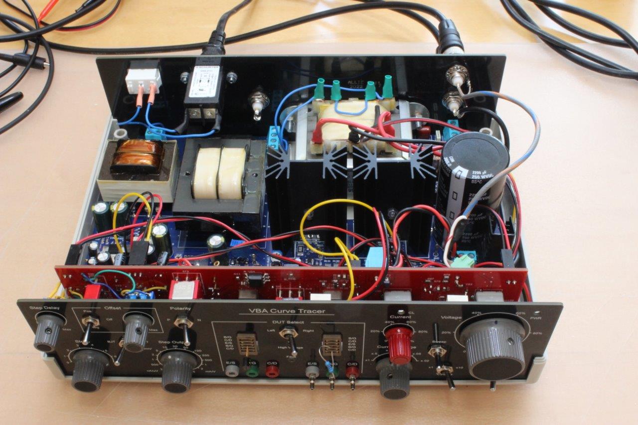
3.1 What “building it” means here
The VBA is a from-published-files build, not a purchasable kit. There is no vendor, no bagged BOM, and no support line. What exists instead is a complete, public design package in the paulvee/VBA-Curve-Tracer GitHub repository: schematics, 2D and 3D board renders, bills of materials, connector and wiring lists, build instructions, verification-and-calibration procedures, and the Gerber sets for all four PCBs. Mark Allie did the EDA work — capturing the schematics and laying out the boards, and moving most of the design to surface-mount parts. Paul Versteeg (paulvee) is the originator and documents the build across his blog; Bud Bennett contributed to the circuit development. The README additionally credits Matt Web and Cory Lytle for catching BOM part-number errors and improving the installation and calibration instructions — they are not part of the “VBA” name (Versteeg / Bennett / Allie) but their fixes are baked into the current revisions.
You fabricate the four boards from the shared Gerbers, source the parts against the BOMs, wire the transformer and panel, and bring the instrument up on the bench. Nothing about the result is a microcontroller project: the VBA is fully analog. There is no firmware to flash, no host application to install, and no PC in the signal path. The oscilloscope you already own is the display — the finished tracer outputs X, Y and Z (blanking) signals and you read the I-V curves on a CRT scope or a DSO switched to X-Y mode. That shapes the whole build: everything you assemble is analog signal-conditioning and power hardware, and “bring-up” means getting real voltages and currents right, not debugging code.
This volume is an orientation to the design files and to the practical assembly and bring-up. It is not a substitute for the repository’s own build and calibration PDFs, which are the authoritative, load-bearing documents. Where this volume gives an outline, the repo gives the step-by-step.
3.2 The four boards
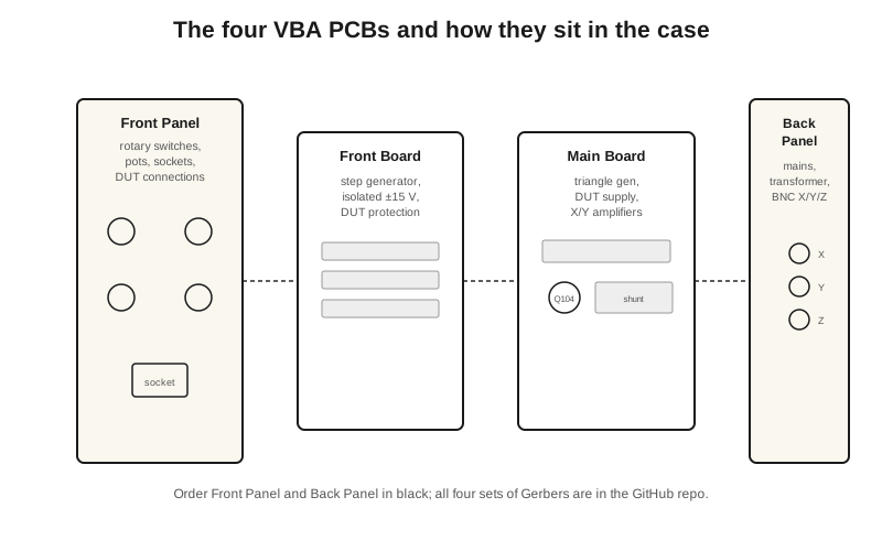
The instrument is partitioned across four PCBs, each with its own folder, BOM and Gerber set in the repository:
Table 1 — The instrument is partitioned across four PCBs, each with its own folder, BOM and Gerber set in the repository
| Board | What it carries |
|---|---|
| Main Board | Triangle sweep generator, the regulated DUT supply (transconductance/error amp driving the power-MOSFET pass devices), current-limit reference and current-sense shunt, the X and Y output amplifiers, and the local low-voltage power rails |
| Front Board | The isolated step generator (producing the 0-7 staircase), its floating +/-15 V supply, step buffering and offset, the current/voltage set circuitry, and the DUT-protection / fault-detect logic |
| Front Panel | The user interface — rotary switches, potentiometers, toggle switches and indicator LEDs — plus the DUT connections: the banana posts and the Left/Right device sockets used for matched-pair work. Doubles as the visible front face of the instrument |
| Back Panel | Mains inlet and line filter, the DUT-supply transformer, and the X / Y / Z BNC output connectors that feed the scope. Doubles as the visible rear face |
The split is deliberate. The two “panel” boards are structural as well as electrical — they are the front and rear faces of the enclosure, with the silkscreen doing double duty as the panel legend. Because those two boards become the visible faces, their solder-mask colour is a cosmetic choice worth making deliberately when you order fabrication, whereas the internal Main and Front boards’ mask colour does not show.
Before populating anything, study the 3D renders in each board folder. They show component orientation and clearances — the two facts that bite hardest during assembly — and they matter most around the heatsinked pass devices, where a wrong-way transistor or an under-spec clearance is a rework rather than a re-solder.
3.3 The design files and BOMs
The repository is organised so that each board’s schematics, BOM, layout and Gerbers travel together. The documents that carry the build:
- Schematics — one set per board. The Main Board’s sheets are split by function (the triangle generator, the DUT supply, the current source and sense, and the several local supply rails); the Front Board’s sheets are likewise split (the step generator, the step buffering and offset, the current-and-voltage set, the fault-detect, and the X/Y amplifier interface). Read these alongside the block-level descriptions in Vol 2 — the sheet names map onto the functional blocks described there.
- Bills of materials — on-board parts are listed per board. The off-board parts (rotary and toggle switches, potentiometers, panel connectors, sockets and hardware) are collected in a separate off-PCB parts BOM, and there is a dedicated connector and wiring list that defines every inter-board and panel wire. These two are as load-bearing as the schematics: a large fraction of the build is wiring, not soldering.
- Gerbers — one set per board, ready to hand a fab house.
- Build instructions — separate install notes for the Front Board and the Main Board.
- Specifications and Verification and Calibration — the performance envelope and the step-by-step alignment procedure. These govern bring-up and are covered only in outline below.
One recurring caution runs through the file history: use the latest BOM revision and read the recent-changes notes before you order. The corrections credited to Matt Web and Cory Lytle exist precisely because early revisions had part-number errors and availability problems; builders have folded fixes back in over successive revisions. Two errata are worth knowing because they change parts you will actually stuff: later revisions added a 12 V protection Zener and changed R146 to 1k8 to cure EMI and oscillation seen with long DUT leads. Order against a stale BOM and you will fight a solved problem.
3.3.1 The transformer is the one part that needs thought
The three DUT-supply envelopes are not three separate supplies — they are one supply, with the three ranges set by the transformer and its wiring configuration per the repository’s documentation. The ranges are:
Table 2 — The three DUT-supply envelopes are not three separate supplies — they are one supply, with the three ranges set by the transformer and its wiring configuration per the repository's documentation. The ranges are
| Voltage range | Current limit |
|---|---|
| 0-35 V | up to 2 A |
| 0-70 V | up to 1 A |
| 0-200 V | up to 100 mA |
Per the repository documentation, those three envelopes are set by the transformer and wiring configuration rather than by three separate supplies. Getting the transformer and its wiring right is a prerequisite for the supply behaving at all, so follow the repository’s transformer and connector/wiring documentation exactly. This is not a place to improvise a substitute transformer from memory of the ratings; the transformer and its wiring are part of the design, not an implementation detail.
The 200 V range also drives the choice of reservoir capacitor. It is not a single high-voltage part: it is two 1000 uF / 100 V (85 C) electrolytics in series, giving roughly a 200 V effective rating and about 500 uF of bulk. The series pair absorbs the transients thrown off by range switching so the DUT supply does not spike. Buy this to spec — the voltage rating, the series arrangement, and the 85 C temperature grade all matter — and note that it stays charged after power-off (see the safety notes below).
3.4 Assembly notes
A build order consistent with the repository’s structure, and with the reality that the panels are structural:
- Populate the Main Board and Front Board from their per-board BOMs. Fit the passives first, then the semiconductors, then the power-MOSFET pass devices and their heatsinks. On the 35 V / 2 A range the pass devices dissipate real power — the supply is a linear regulator dropping the transformer rail down to the DUT voltage, so at 35 V out and 2 A the dissipation in the pass stage is substantial. Mount and heatsink them per the layout; this is where thermal design is not optional.
- Wire the DUT-supply transformer and the power rails, following the connector/wiring list. Bring up the raw supplies before any active bring-up and confirm each rail independently: the DUT-supply reservoir, the isolated +/-15 V step-generator rails, and the X/Y and control rails — each present, at the right polarity, and at the right voltage. Respect the isolation barrier around the step generator: do not bond its floating ground to chassis. The step generator drives the control terminal of the DUT and must float relative to the swept main terminal; accidentally grounding it defeats that and can put the fault-detect or the DUT at risk.
- Mount the Front Panel controls and wire them back to the Front Board per the wiring list. The panel carries the confirmed controls: Step Delay (the cycle delay, ~40-250 ms, for thermal relief of the DUT); Offset (which can be switched off; ~±2 V standard, ~±10 V with the optional mod); Polarity (P or N device selection); Steps (0 through 7); the Step Output magnitude selector (the 1-2-5 sequence); DUT Select (Left / Right) with the E/S, B/G, C/D banana posts and the two device sockets for matching; Current and Voltage level controls with the CL (current-limit) indicator; the Current Range multiplier; and the Voltage Ranges selector. The DUT itself connects via 2 mm connectors; note that the B/G (base/gate) drive lines carry a series inductor to kill parasitic oscillation, with optional sub-100 pF caps to ground — fit these as the layout shows, because oscillation on the control terminal is a common failure and the fix is designed in.
- Fit the Back Panel with the mains inlet and line filter, the transformer connections, and the X / Y / Z BNC outputs that feed the scope.
The physical result is a plastic-enclosure instrument of roughly 25 x 18 x 8 cm and about 2.5 kg — a compact bench box, not a rack instrument. It runs from 230 V mains, drawing about 250 mA (~12.5 W) at idle and rising to about 340 mA (~53 W) at maximum load. Those are modest numbers, but the mains and high-voltage sections are not.
3.4.1 Two safety points that apply squarely here
The instrument contains mains wiring and a 200 V DUT supply with a large series-pair reservoir capacitor that stays charged after power-off. Treat it like any mains-connected, high-voltage bench tool: discharge the reservoir before working inside, and bring it up for the first time behind a current-limited variac if you have one, so a wiring error trips a limit instead of a device. The general bench-discipline rules for mains and HV work in the shared notes apply directly to this build.
3.5 Bring-up and calibration
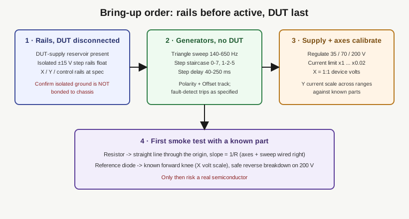
Once the rails check out, follow the repository’s Verification and Calibration procedure rather than improvising. It is written to be worked in order, and the order matters — you confirm passive infrastructure before energising anything that can be damaged. In outline, bring-up confirms:
- The triangle sweep generator runs. Its frequency is adjustable across roughly 140 Hz to 650 Hz; the sweep drives the main-terminal (collector/drain) voltage and provides the X-axis. Confirm it is clean and that the sweep synchronises to the step transitions — a sweep that free-runs against the steps smears the trace family.
- The step generator produces a clean staircase. It makes 0 to 7 steps per sweep cycle (up to eight traces including the zero step), selectable in a 1-2-5 sequence from 5 V / 5 mA at the top down to 50 uV / 50 nA at the most sensitive setting. Confirm Polarity flips the family correctly for N- vs P-type devices, that Offset shifts the family as expected (the standard range is about +/-2 V, with an optional modification extending it to about +/-10 V for JFETs that need VGS beyond about -5 V), and that the Step Delay stretches the per-cycle dwell across its ~40-250 ms range.
- The DUT supply regulates across all three ranges (35 V / 2 A, 70 V / 1 A, 200 V / 100 mA) and its current limit tracks the front-panel Current Range multipliers. There are six of them — x1, x0.5, x0.2, x0.1, x0.05, x0.02 — and the current-limit setting should scale correctly across all six. Verify the CL indicator lights when the DUT hits the limit.
- The fault-detect / protection behaves. Confirm it trips on the fault conditions the design targets (this is what protects both the DUT and the pass stage), and that the added 12 V protection Zener and the R146 = 1k8 change are in place if you built from an older revision.
- The X and Y amplifiers are calibrated. Trim X to a 1:1 device-voltage scale and Y for correct current scaling across the current ranges. Known parts are the fastest way to prove the axes read true.
3.5.1 First smoke test with known parts
After calibration, the natural first trace is a plain resistor. In X-Y it should draw a straight line through the origin, its slope set by the resistance and the selected current range — slope equals 1/R for a Y-axis reading current against an X-axis reading voltage. A crooked line, a line that misses the origin, or a slope that does not match the resistor tells you an axis is mis-scaled or a lead is on the wrong terminal, and it tells you that before you risk a semiconductor.
A reference diode is the natural second test. Its known forward knee (about 0.6-0.7 V for a silicon junction) confirms the X-axis voltage scale, and stepping it into reverse — into a Zener’s breakdown, or a rectifier’s reverse leakage on the 200 V range under a safe current limit — exercises the high-voltage path with a part whose behaviour you already know. Only once a resistor and a diode both read correctly is the instrument trustworthy for the unknown parts and the worked measurements in Vol 4.
3.6 Sourcing and cost notes
Because the VBA is a published-files design rather than a stocked kit, plan on gathering parts from the usual distributors against the BOMs, and plan on lead time. The parts that dominate both cost and schedule are the DUT-supply transformer, the enclosure, the rotary switches and the front-panel hardware — order those first, because they are the long-pole items and the transformer in particular is the one part you cannot casually substitute. The active silicon is not exotic, but the power-MOSFET pass devices and their heatsinking, and the series-pair reservoir capacitor, are worth buying exactly to spec rather than substituting on availability: the pass devices set the thermal envelope and the reservoir sets the transient behaviour of the 200 V range.
The community-maintained BOM revisions are the other sourcing reality. They exist because builders hit part-availability and errata issues, so cross-check the latest revision and the repository’s recent-changes notes and issue history before committing an order. It is cheaper to read the changelog than to re-order.
With the four boards populated, the transformer and rails verified, the fault-detect confirmed to trip, and the X and Y axes calibrated against a known resistor and diode, the instrument is ready for the component measurements in Vol 4.