B&K Dynamic 375 VTVM · Volume 1
B&K Dynamatic 375 — Vol 1: Overview — What a VTVM Is & Why It Still Earns Bench Space
An 11-megohm needle from 1961 still tells the truth about a grid-bias node that a modern 10-megohm DMM only approximates.
1.1 Why a VTVM, and why an analog needle, in 2026
A vacuum-tube voltmeter earns its bench slot for one electrical reason and one human-factors reason, and both still matter on a tube-circuit bench.
1.1.1 What problem the VTVM class was built to solve
Before solid-state test gear existed, the only voltmeters on a bench were passive analog movements — a coil, a spring, and a needle, deflected directly by the current the circuit under test could supply through the meter’s own resistance. That’s the sensitivity figure printed on every classic VOM (20 kΩ/V, 5 kΩ/V, and so on): it’s a statement of how much current the meter itself needs to move the needle, and by construction that current has to come from the circuit being measured. On a power supply rail or a filament winding, pulling a little current is harmless. On a tube’s control-grid circuit — where the whole point of the surrounding megohm-range resistors is to keep grid current at essentially zero — a passive meter’s own current draw is enough to falsify the reading, sometimes badly. VTVMs exist to break that link, interposing a tube (later a FET) as an active buffer so the meter movement is driven by an amplified, low-impedance replica of the signal, while the actual measurement point sees only the tube’s grid — a near-open circuit. That’s the general principle behind every instrument in the class, including this one; §2 below and Vol 2 cover exactly how the 375 implements it.
1.1.2 The electrical reason: it barely loads the circuit
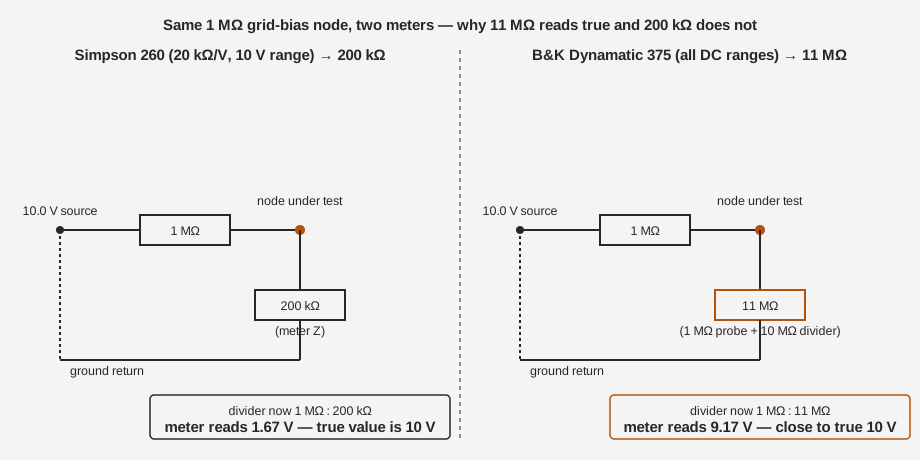
Every voltmeter is also a resistor across the node you’re trying to measure. A garden-variety 20 kΩ/V analog VOM — say a Simpson 260 — presents an input resistance that changes with range: on a 10 V DC range that’s only 200 kΩ, and on a 2.5 V range it’s a mere 50 kΩ. Against a low-impedance node (a cathode, a filament supply) that’s harmless. Against a grid-bias network, an AVC (automatic volume control) line, or a screen-grid dropping-resistor node — all of which are commonly built from megohm-range resistors specifically because almost no current is supposed to flow there — a 200 kΩ meter doesn’t read the voltage, it changes it. The meter becomes part of the divider it’s trying to measure, and the needle reports a fiction.
A VTVM sidesteps the problem by putting a vacuum tube’s high-impedance grid, not the meter movement itself, across the node. The B&K Dynamatic 375 presents 11 MΩ on every DC range — one number, constant, regardless of what range you’ve dialed in — because the range switch only changes the attenuation ahead of that fixed-impedance grid, not the impedance the circuit sees. Against most tube-circuit source impedances (typically tens to hundreds of kΩ), 11 MΩ is close enough to a true open circuit that the reading is honest. See Vol 4 §2 for the full loading-error math and a worked comparison against the 260’s 20 kΩ/V figures.
Note — “VTVM” is a legacy name that stuck around even after the circuits inside stopped always using literal vacuum tubes — some later instruments in this class use FETs instead (B&K’s own later Model 277 FET Multimeter is one). The 375 covered in this dive is a true tube VTVM: see §2 below and Vol 2 for the circuit that earns the name.
1.1.3 The human-factors reason: the needle shows rate and direction
A digital multimeter gives you a settled number a few times a second. An analog needle gives you continuous motion — you can watch it swing, hunt, and settle in real time, and you can see which direction it’s moving as you turn a slug-tuned IF transformer or a trimmer capacitor. That’s exactly what peaking and nulling (the core of tube-radio and tube-TV alignment work) requires: you’re not reading a value, you’re driving a value to a maximum or a minimum while your hands are on the adjustment. A digital readout that updates in discrete steps fights that task; a needle doesn’t.
The needle also needs no logic board, no firmware, and no battery for the voltage/AC functions — only warm-up. Power it on, let the 12AU7 bridge tube reach thermal equilibrium, zero it, and it’s ready. That simplicity is a virtue on a bench where the point is diagnosing someone else’s electronics, not troubleshooting your test instrument’s own firmware.
Note — none of this makes the VTVM strictly better than a modern DMM — see §4’s when-to-use table. It makes the VTVM the right tool for a specific, still-common job: high-impedance DC nodes in tube circuits, read while your hands are busy peaking an adjustment.
1.2 What this unit is
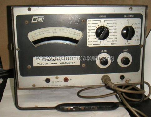
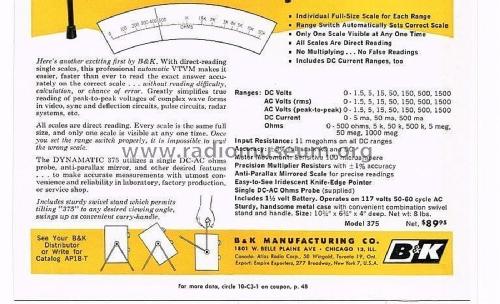
The B&K Dynamatic 375 is a bench VTVM built by B&K Manufacturing Co., 1801 W. Belle Plaine Ave., Chicago, Illinois — the company that later became Dynascan Corp. and survives today as the test-gear brand B&K Precision, still selling bench meters, oscilloscopes, and power supplies as of this writing. [CONFIRMED — ad footer + radiomuseum indexing the model under “B&K Precision, Dynascan Corp., Cobra”] It was introduced in 1961 at an original price of $89.95 (radiomuseum lists $90.00, a rounding difference), and production apparently ran into the mid-1960s — one period listing is dated 1964, consistent with a multi-year run rather than a single model year. [CONFIRMED price/intro year; LIKELY on the extended production window]
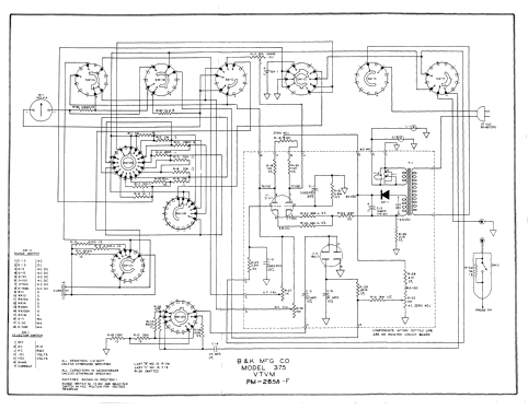
It is a genuine vacuum-tube instrument, not a solid-state or FET design: the measuring path runs through one 12AU7 dual-triode (the balanced-bridge DC amplifier) and one 6AL5 dual-diode (the AC rectifier), with a selenium rectifier supplying B+ for the tube’s plate voltage. Vol 2 covers this circuit in full; Vol 3 covers the physical chassis and controls.
Note — lineage, stated once so it doesn’t get muddled downstream. The 375 (1961, tube, drum scale) is the earliest of a three-model B&K VTVM family, not the newest. It was followed by the 177 (~1970, also a 12AU7 + 6AL5 tube VTVM, but with a plainer flat printed scale and a battery-less, rectified-AC ohms supply) and then the 277 “FET Multimeter” (~1972–1982, genuinely solid-state, ~15 MΩ DC input, a different PR-21 probe with a 100 kΩ isolation resistor instead of 1 MΩ). Read the family as 375 → 177 → 277, tube giving way to FET only at the very end of the line. [CONFIRMED — radiomuseum dates for all three models]
1.2.1 The signature feature: the “Dynamatic” rotating drum scale
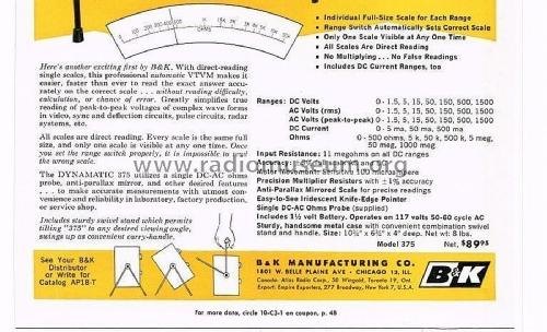
Most multi-range analog meters cram every range’s scale onto one crowded meter face, forcing you to find the right printed arc among six overlapping ones and mentally apply a multiplier. The 375 does something different, and it’s the feature the model name commemorates: an individual, full-size scale is printed for every range around the outside of a rotating drum, and turning the RANGE switch mechanically rotates the correct scale into a single lighted window. Only one scale — the right one, already scaled correctly — is ever visible. B&K’s own 1961 ad copy: “Individual Full-Size Scale for Each Range / Range Switch Automatically Sets Correct Scale / Only One Scale Visible at Any One Time / All Scales Are Direct Reading / No Multiplying — No False Readings.” [CONFIRMED — 1961 advertisement] The drum is illuminated, which is where “Dynamatic” comes from as a trade name silk-screened on the panel. [LIKELY — period seller descriptions, consistent with the lighted-window design]
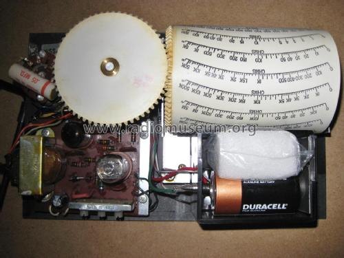
This drum-and-linkage assembly is also, per service-forum accounts, “unique to these instruments” — there is no parts-bin substitute if it’s damaged, which makes it the single most fragile and most irreplaceable mechanism in the unit. [LIKELY — forum]. Vol 5 covers refurbishing implications.
1.2.2 In the box: case, stand, and the probe complement
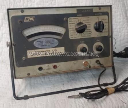
The case is metal, fitted with a combination swivel-stand/tilt-bail handle — the same fold-out bail common across the era’s bench meters, doubling as a carry handle and a prop that angles the drum window up toward the operator. Overall footprint is compact for a bench instrument: 10½ × 6½ × 4 in per the 1961 ad, 10½ × 6 × 4 in (267 × 152 × 102 mm) per radiomuseum’s listing — the two sources disagree by half an inch on the middle dimension — and ~8 lb net either way. [CONFIRMED — 1961 ad; radiomuseum]
A single DC-AC-Ohms probe is supplied with the instrument and does triple duty: it carries the 1 MΩ series resistor that forms half of the 11 MΩ DC input (see §1 above), and per the standard design convention B&K used across its probe line, that resistor is switched out of circuit for the AC and Ohms functions. [CONFIRMED probe supplied; the 1 MΩ-switching detail is LIKELY by analogy to sibling B&K probes — see Vol 3 §4 for the full probe-internals discussion.] A separate RF demodulator probe (rated to roughly 250 MHz) extends the same meter to RF/IF envelope measurements and is documented alongside the 375 in the manual package, though it reads as an accessory rather than a standard-supplied item — see §4’s when-to-use table and Vol 3 §4 for probe-selection guidance.
1.2.3 Not just volts and ohms: DC current ranges
Where most VTVMs are strictly volts-and-ohms instruments, the 375 is unusual in also offering DC current ranges (5 mA, 50 mA, 500 mA), brought out to dedicated DC CURRENT jacks at the bottom of the panel. [CONFIRMED — 1961 ad: “Includes DC Current Ranges, too”]. Unlike the voltage functions, current measurement necessarily means breaking the circuit and inserting the meter in series — there’s no way around that with any ammeter, tube-buffered or not — so these ranges are the exception to the “barely loads the circuit” story in §1: on the DC current jacks, the 375 behaves like a conventional series ammeter, not a high-impedance voltage probe. They’re most useful for spot-checking plate current or cathode current in a tube stage where a schematic gives you an expected milliamp figure to check against. Full range tables and the current-measurement procedure live in Vol 3 and Vol 4 respectively.
1.2.4 The two-VTVM bench
Jeff runs the 375 side by side with a Simpson 311-2 VTVM as a deliberate cross-check pair, not a redundant spare. The two instruments share the same job — a ~11 MΩ high-impedance DC/AC/ohms voltmeter for tube-circuit work — built by different manufacturers on different bridge and rectifier topologies. When a reading looks suspicious (drift, an unexpected null, a suspected bad probe or a suspected fault in the circuit under test rather than the meter), swapping to the second VTVM on the same node is a fast way to separate “the circuit is really doing that” from “my meter has drifted.” Vol 6 covers the cross-check workflow, discrepancy triage, and each instrument’s individual quirks in detail.
The value of running two different VTVMs, rather than one VTVM plus a spare of the same model, is that a systematic error specific to one design — a drifted bridge-balance pot, an aging rectifier diode, a precision resistor that’s crept upward with age (see Vol 5’s carbon-comp drift discussion) — shows up as a disagreement between the two instruments instead of silently passing unnoticed on a single meter reading against itself. A third instrument on the same bench, the Simpson 260 VOM, rounds out the trio for the opposite reason: it’s the fast, no-warm-up tool for the low-impedance nodes where loading doesn’t matter and speed does, freeing both VTVMs for the high-Z work they’re built for. See §4’s when-to-use table for the full division of labor.
1.3 Headline specs
Table 1 — Headline specs
| Parameter | B&K Dynamatic 375 | Confidence |
|---|---|---|
| Type | Vacuum-tube VTVM (12AU7 bridge + 6AL5 rectifier + selenium B+) | CONFIRMED |
| Introduced | 1961, ~$89.95 | CONFIRMED |
| DC input resistance | 11 MΩ, all DC ranges (1 MΩ probe tip resistor + 10 MΩ internal divider) | CONFIRMED |
| Meter movement | 100 µA full scale; anti-parallax mirrored scale, iridescent knife-edge pointer | CONFIRMED |
| Movement type | Most likely jeweled-pivot D’Arsonval — not confirmed taut-band | UNCERTAIN |
| DC volts | 1.5 / 5 / 15 / 50 / 150 / 500 / 1500 V (7 ranges), + polarity reversal (DC+/DC−) | CONFIRMED |
| AC volts | Same 7-range cascade, separate RMS and peak-to-peak functions | CONFIRMED |
| DC current | 5 mA / 50 mA / 500 mA (3 ranges) — unusual for a VTVM | CONFIRMED |
| Ohms | 500 Ω / 5 k / 50 k / 500 k / 5 meg / 50 meg / 1000 meg (7 ranges); internal 1.5 V D-cell | CONFIRMED |
| Multiplier resistor accuracy | ±1% | CONFIRMED |
| RF probe | Demodulator probe, rated to ~250 MHz (accessory, not standard-supplied) | LIKELY |
| dB scale | None found in verified sources | NOT FOUND |
| Size / weight | 10½ × 6½ × 4 in (ad) / 10½ × 6 × 4 in (267 × 152 × 102 mm) (radiomuseum), ~8 lb net | CONFIRMED |
| Power | 117 V, 50–60 Hz mains | CONFIRMED |
Note — confidence tags used in this volume: CONFIRMED = primary and/or multiple sources agree, LIKELY = one decent source, UNCERTAIN = thin/conflicting, NOT FOUND = could not verify. Where a figure is UNCERTAIN or NOT FOUND above, later volumes repeat the caveat rather than silently asserting a number.
The ohms range cascade is logarithmic, as it has to be to span roughly six decades (500 Ω to 1000 MΩ, i.e. 1000 megohms) on one dial: 500 Ω · 5 k · 50 k · 500 k · 5 meg · 50 meg · 1000 meg. Each range steps the prior one by roughly a decade, except the top range — 50 MΩ to 1000 MΩ is a ×20 jump, not ×10, so a clean ×10-per-step ladder would have topped out at 500 MΩ instead. Reading an unknown resistor is still a matter of picking the range where the needle lands mid-scale, exactly the same operating discipline as any ohmmeter of the era — the difference here is that the current used to make that reading comes from the meter’s own internal 1.5 V D-cell rather than from the circuit under test, which is why ohms measurements on a VTVM (like on any ohmmeter) are only valid with the circuit powered off and the component isolated. Vol 3 covers the full range tables including the AC peak-to-peak vs. RMS split; Vol 4 covers ohms measurement procedure and the OHMS-adjust zeroing step.
⚠ Danger — the 375 is a mains-powered tube instrument: it draws 117 V AC directly, develops internal B+ well above that through its power transformer, and rectifies it through a selenium rectifier — a component that can emit an acrid, mildly toxic odor if it fails and overheats, and that some restorers replace pre-emptively with a silicon diode for that reason (see Vol 5). Treat the chassis as line-connected any time it’s plugged in, follow the one-hand rule above roughly 50 V, and read
_shared/legal_ethics.mdbefore opening the case. Vol 4 covers safe operating procedure in full; Vol 5 covers safe servicing.
A word on the two rows flagged UNCERTAIN above, since a hostile reading of a spec sheet should never paper over a gap: neither the 1961 ad nor radiomuseum’s listing states the meter movement’s pivot technology outright. A 100 µA movement built in 1961 is most consistent with a conventional jeweled-pivot D’Arsonval design — taut-band suspensions existed by then but weren’t yet the default across the industry (compare the Simpson 260’s deep dive, where taut-band didn’t become standard on that product line until roughly 1973) — but “most consistent with” is an inference, not a manual citation, and this dive says so rather than asserting a crisp answer it can’t back up. Similarly, the ad’s overall-accuracy figure (as opposed to the ±1% multiplier-resistor tolerance, which is clearly printed) sits behind a watermark in the only scan located; typical era VTVMs of this class ran roughly ±3% of full scale on DC and ±5% on AC, and the 375 is plausibly in that neighborhood, but the exact printed number remains unverified. Both gaps are candidates for resolution if a cleaner manual scan turns up — see Vol 3 §1 for where this dive would update if that happens.
1.4 VTVM vs. VOM vs. modern DMM — when to reach for which
No single instrument wins every bench task. The table below is the quick-reference version; Vol 4 §2 and Vol 6 work through the loading-error arithmetic and specific tube-circuit scenarios in depth.
Table 2 — VTVM vs. VOM vs. modern DMM — when to reach for which
| Task | Best tool | Why |
|---|---|---|
| Grid-bias, AVC, screen-supply, other high-Z tube nodes | VTVM (375 or 311-2) | 11 MΩ constant input barely loads a megohm-range source; a 20 kΩ/V VOM changes the reading it’s trying to take. |
| Peaking/nulling an IF transformer or trimmer (alignment) | VTVM, needle | Continuous analog motion shows rate and direction while your hands stay on the adjustment; a digital readout updates in discontinuous steps. |
| Fast go/no-go check: filament voltage, B+ rail, continuity | VOM (Simpson 260) or DMM | Low source impedance means loading is a non-issue; no warm-up beats an 11 MΩ VTVM that needs to stabilize first. |
| Quick field/on-the-bench current or resistance spot-check | VOM or DMM | VTVM current ranges exist on the 375 but are a secondary feature; a VOM/DMM is faster to set up for a quick check. |
| Precision DC voltage, auto-ranging, data logging | Modern DMM | Digital accuracy and resolution (and often 10 MΩ+ input, true-RMS AC) beat a 1961 needle for absolute precision and repeatability. |
| Cross-checking a suspect reading against drift/fault | Second VTVM (the two-VTVM bench) | Swapping instruments on the same node separates “meter drifted” from “circuit is really doing that” without reaching for a third, differently-behaved tool. |
| RF/IF signal presence, up to ~250 MHz | VTVM + RF demodulator probe | The AC/DC bridge reads the demodulated envelope; most modern DMMs have no comparable accessory probe ecosystem for tube-era gear. |
⚠ Note — a modern 10 MΩ-input DMM narrows the loading-error gap on high-Z nodes considerably versus a 20 kΩ/V VOM, but it still doesn’t match the 375’s 11 MΩ, and it trades away the analog needle’s rate/direction feedback that alignment work depends on. The VTVM’s advantage on this bench is the combination of high input impedance and analog display, not either alone — see Vol 4 §2 for the numbers.
1.4.1 A worked example: why the tool choice isn’t academic
Consider a tube receiver’s AVC line — the DC control voltage, typically developed across a resistor in the megohm range, that the receiver feeds back to earlier stages to tame gain as signal strength changes. Probe that line with the Simpson 260 on its most sensitive DC range and the 200 kΩ meter resistance can pull a real -3 V AVC voltage down to a fraction of that, making a perfectly healthy AVC system look weak or dead — exactly the kind of false lead that sends a repair down the wrong path. Probe the same line with the 375, and the 11 MΩ input barely disturbs the megohm-range source impedance; the reading is close enough to true that a fault diagnosis based on it is trustworthy. The same logic applies to grid-bias resistors, screen-dropping-resistor taps, and any other node built deliberately high-impedance by the original circuit designer — which, in tube gear, is most of the interesting nodes.
Now flip the scenario: checking a 6.3 V filament winding for correct AC voltage. Here source impedance is a fraction of an ohm, so a 5 kΩ/V VOM’s loading is utterly irrelevant, and the VOM’s zero-warm-up, grab-and-read speed wins outright. The tool selection isn’t about one instrument being generally “better” — it’s about matching input impedance to source impedance for the specific node in front of you, which is exactly what the table above is for.
1.5 Depth index — where the rest of this dive goes
This is Volume 1 of a six-volume deep dive. The remaining five volumes go deep on mechanism, hardware, operation, and maintenance:
- Vol 2 — How a VTVM Works. The 12AU7 balanced-bridge DC amplifier in detail (how cathode-coupled bridge unbalance turns into a meter deflection), the 6AL5 AC rectifier path (RMS vs. peak-to-peak), the internal-battery ohms circuit, and the selenium-rectifier B+ supply. Schematic-driven.
- Vol 3 — Inside This Unit. Full hardware tour: chassis layout, every front-panel control and jack, the complete range tables, the drum-scale mechanism’s mechanical linkage, and the RF demodulator probe.
- Vol 4 — Using It. Step-by-step operating procedure (warm-up, zeroing, function/range selection,
polarity reversal), probe technique, the loading-error math promised above, and mains/HV bench
safety per
_shared/legal_ethics.md. - Vol 5 — Calibration & Refurbishing. The known grounding gotcha on the ZERO/OHMS pots, carbon-comp divider drift in the precision string, battery-holder corrosion, and a recalibration procedure against a known DC standard.
- Vol 6 — Cheatsheet & the Two-VTVM Bench. One-page quick reference plus the full cross-check workflow with the Simpson 311-2, including where each instrument’s individual quirks tend to disagree and how to arbitrate them.
Sources
- radiomuseum.org — B&K Dynamatic 375 (model year, tube complement, selenium B+, price, size, schematic and photo set): https://www.radiomuseum.org/r/dynascan_k_dynamatic_375.html
- radiomuseum.org — 1961 advertisement spec block (ranges, 11 MΩ input, 100 µA movement, 1½ V battery, ±1% multipliers, size/price): https://www.radiomuseum.org/images/radio/b_k_dynascan_corp/b_k_dynamatic_375_2105857.jpg
- radiomuseum.org — schematic image (title block “B&K MFG CO MODEL 375 VTVM,” drawing no. PM-285M-F): https://www.radiomuseum.org/images/schematic-medium/b_k_dynascan_corp/b_k_dynamatic_375_2095388.png
- BAMA manual archive — B&K 375 (
bk375.djvu, includes AE-1A and PR-38 RF probe documentation and the 1961 ad): http://bama.edebris.com/manuals/b&k/375 - elektrotanya — “B-K DYNAMATIC-375 TUBE VOLTMETER” service manual, 24 pp: https://elektrotanya.com/b-k_dynamatic-375_tube_voltmeter.pdf/download.html
- Antique Radio Forums — “B&K Dynamatic 375 VTVM woes” (grounding fix, precision-divider values, battery wiring, tube complement): https://antiqueradios.com/forums/viewtopic.php?p=1517272, https://antiqueradios.com/forums/viewtopic.php?p=1517468, and https://www.antiqueradios.com/forums/viewtopic.php?t=3786
- Surplus Sales of Nebraska — B&K RF Demodulator Probe (AV-1A class, “to 250 MHz, for most VTVMs”): https://www.surplussales.com/items/99536/bk-rf-demodulator-probe/
- byan-roper.org (Steve Byan) — switchable VTVM probe design notes, covering the B&K PR-43 (177) and PR-21 (277) probes: https://www.byan-roper.org/steve/steve-at-play/antique-electronics-and-2/switchable-vtvm-probes.html
- radiomuseum.org — B&K 177 VTVM (~1970, successor model): https://www.radiomuseum.org/r/dynascan_precision_model_vtvm_177.html
- elektrotanya — B&K 277 solid-state FET multimeter, 1982 manual (confirms the 277 as the later, solid-state successor): https://elektrotanya.com/bk-precision_277_sollid_state_electronic_multimeter_1982_instr._sm.zip/download.html