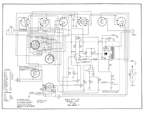
B&K Dynamic 375 VTVM · Volume 3
B&K Dynamatic 375 — Vol 3: Inside This Unit — Hardware, Controls & Ranges
A guided tour of the instrument itself — the rotating drum, the tube complement, the control layout, and every range it reads.
3.1 Scope of This Volume
Vol 1 introduced the VTVM as a class of instrument and made the case for keeping one on the bench. Vol 2 worked through the theory — the balanced bridge, the AC rectifier, the ohms circuit. This volume sets theory aside and describes the physical instrument: what’s under the handle, what every knob does, what the tube complement is, and — the two things that make this particular VTVM worth owning over a generic period-correct one — the rotating illuminated “Dynamatic” drum scale and the somewhat unusual built-in DC current ranges. Circuit-level explanation of why the bridge and rectifier work the way they do is Vol 2’s job; this volume is the parts list, the panel map, and the spec table an engineer reaches for mid-repair or mid-measurement.
Everything below is sourced from the 1961 advertisement’s spec block, the radiomuseum photo/schematic set, and a service-forum thread that documents actual part designators inside the chassis (see Sources). Where a number could not be verified against a primary source, that is stated plainly rather than guessed — a recurring feature of working from a 65-year-old instrument whose full service manual sits behind two gated download hosts (see Vol 5 for the manual-access story).
Note — This is the hardware volume. Using the instrument (warm-up, zeroing, probing technique, safety) is Vol 4. Calibration and refurbishing procedure — including the exact fix for the 375’s best-documented failure mode — is Vol 5.
3.2 Physical Overview & Case
The 375 ships in a two-tone gray steel case with a combination swivel‑stand / tilt‑bail handle — the same fold-down wire bail that doubles as a viewing-angle stand, a design convention shared across almost every panel-meter test instrument of the era (it reappears nearly identically on the sibling Simpson 311‑2 covered in the Simpson 311‑2 VTVM dive). Flip the bail down and out, and the case props itself up at a comfortable reading angle on the bench; fold it flat and it becomes a rudimentary carrying handle.
Table 1 — Physical Overview & Case
| Physical spec | Value | Confidence |
|---|---|---|
| Case material | Metal (steel), painted | [CONFIRMED] |
| Stand/handle | Combination swivel-stand / tilt-bail | [CONFIRMED] |
| Dimensions | 10½ × 6½ × 4 in (≈ 267 × 152 × 102 mm, per radiomuseum’s slightly different W/D reading) | [CONFIRMED] |
| Net weight | ~8 lb (≈ 3.6 kg) | [CONFIRMED] |
| Line power | 117 V, 50–60 Hz | [CONFIRMED] |
| Original price | $89.95 (1961 ad); radiomuseum lists $90.00 | [CONFIRMED] |
| Introduced | 1961; production apparently ran into the mid-1960s (one dealer listing dated 1964) | [CONFIRMED] / [LIKELY] |

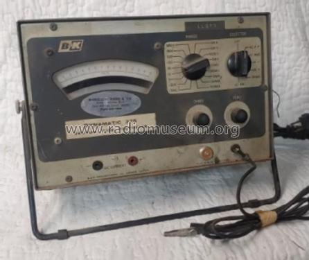
At 8 lb and roughly the footprint of a large hardback book, the 375 is meant to live on the bench permanently, not to be carried into the field the way a Simpson 260 VOM rides in a service tech’s bag (see the Simpson 260 Series 8 dive for that comparison). It needs mains power to operate at all — the tube bridge and its heaters draw current continuously whenever the SELECTOR is off OFF — which is the tradeoff every VTVM makes for its high input impedance and stable zero.
The case livery itself — two-tone gray, black-lettered legends, the “DYNAMATIC” wordmark distinct from the “VACUUM TUBE VOLTMETER” subtitle — matches the general house style B&K used across its early-1960s line, consistent with the same manufacturer’s contemporary signal generators and other bench meters of the period, though no cross-model livery comparison beyond the 177/277 family (§3.5, Vol 1) was located for this dive.
3.2.1 Serial Number, Nameplate & Documented Options
No serial-number range, revision-letter scheme, or factory option list for the 375 was located in the
sources reviewed for this dive — radiomuseum’s listing and the 1961 ad describe a single configuration
with no callouts for optional accessories beyond the two probes already discussed (§3.4–3.5) [NOT FOUND
— options/variants]. That is consistent with a mid-tier, single-SKU instrument of this era and price
point ($89.95), where variant SKUs (if any existed) would more likely show up as a slightly later
cosmetic revision than as a documented factory option list. Jeff’s own unit’s nameplate and serial number
are the authoritative source for this instrument’s specific production date and any deviation from the
1961 baseline spec documented throughout this volume — capture and log them in 00-inventory/ per the
project’s MY_GEAR convention (see the top-level CLAUDE.md) once the unit is photographed.
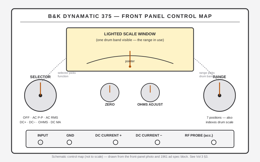
3.3 The Front Panel — Controls & Layout
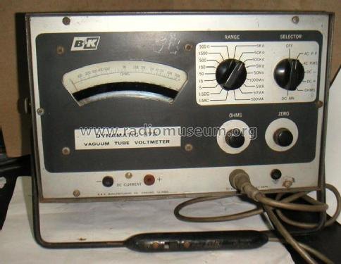
Front-panel nomenclature below is read directly off the panel photograph (radiomuseum
b_k_dynamatic_375_1058470.jpg), which is sharp enough to resolve every silk-screened legend. The panel
reads, top to bottom: the B&K logo and “DYNAMATIC / VACUUM TUBE VOLTMETER” banner; the lighted scale
window; the SELECTOR and RANGE knobs flanking it; the ZERO and OHMS (ohms-adjust) knobs below the
window; and the input/output jacks along the bottom edge.
3.3.1 Function Selector
The SELECTOR knob (left of the scale window) chooses what is being measured. Its seven positions, read directly off the panel:
Table 2 — positions, read directly off the panel
| Position | Function |
|---|---|
| OFF | Instrument off (tube filaments and B+ de-energized) |
| AC P-P | AC volts, peak-to-peak |
| AC RMS | AC volts, RMS |
| DC+ | DC volts, positive polarity |
| DC− | DC volts, negative polarity |
| OHMS | Resistance |
| DC MA | DC current (milliamps) |
Two things about this layout are worth calling out. First, there is no separate polarity-reversal switch or lead-swap procedure for DC — the SELECTOR itself has DC+ and DC− positions, so a technician tracing a negative bias line or an AVC voltage flips the SELECTOR rather than physically swapping the probe and ground lead [LIKELY]. Second, AC is split into RMS and peak-to-peak as two separate SELECTOR positions, not folded into a single AC range with a P-P/RMS toggle elsewhere on the panel or a dB scale — see §7.1 below for why that matters when reading the drum.
Note — No dB scale is present anywhere in the verified spec block or on the panel photo. Given that AC already occupies two SELECTOR positions (RMS and peak-to-peak) and the drum has no visible dB-labeled band, treat “no dB function” as the working assumption for this instrument — flagged [NOT FOUND] rather than [CONFIRMED absent], since the full 24-page service manual (gated, see Vol 5) was not directly readable.
3.3.2 Range Switch
The RANGE knob (right of the scale window) selects which full-scale range within the chosen function — and, uniquely to this instrument, it does double mechanical duty: rotating RANGE also rotates the correct scale into the lighted window (§4 below). There is one range knob shared across all voltage/current/ohms functions; the SELECTOR determines which drum set of seven scales the RANGE position indexes into.
3.3.3 Zero & Ohms-Adjust Controls
Two small knobs sit below the scale window:
- ZERO — balances the 12AU7 bridge with no input applied. Because the bridge’s balance point drifts slightly as the tube warms and ages, ZERO needs to be reset at the start of a session (after warm-up) and periodically thereafter. This is standard VTVM practice, not a 375-specific quirk — see Vol 4 for the warm-up-then-zero sequence.
- OHMS (ohms-adjust) — sets full-scale deflection on the ohms function against the internal 1.5 V cell, with the probe tips shorted together. This compensates for the battery’s state of charge; a tired cell still reads correctly on ohms as long as OHMS-adjust can still reach full scale, and the point at which it can’t reach full scale is the signal to replace the cell (Vol 5 covers this in the refurbishing context).
⚠ Danger — the ZERO and OHMS pots are also the 375’s best-documented failure point. Their bodies ground to the metal case through their mounting hardware, and a loose shaft nut or an oxidized pot-to-case contact is enough to make the meter dead or erratic — a fault that looks like a bad tube or a burned-out bridge component but isn’t. Vol 5 §“Refurbishing Notes” covers the documented fix (clean contacts, star washers rotated to bite fresh metal, shaft nuts tightened) in detail.
3.3.4 Jacks — Probe Input, Ground, DC Current
Along the bottom edge of the panel:
- Input jack — accepts the single supplied DC-AC-Ohms probe (visible plugged in on the front-panel photo) or, as an accessory, the RF demodulator probe (Vol 4 §“Probes”).
- Ground/common jack.
- DC CURRENT jacks — a separate pair of jacks feeding the 5/50/500 mA current ranges (§6 below). These are physically distinct from the voltage/ohms input jack because DC current measurement means breaking the circuit under test and inserting the meter in series, not bridging it across a node — a fundamentally different connection topology from every other function on this instrument.
3.3.5 The Supplied Probe — DC-AC-Ohms
A single probe ships with the instrument and handles DC volts, AC volts, and ohms — there is no separate probe per function [CONFIRMED — ad states one probe is supplied]. The probe tip carries a 1 MΩ series (isolation) resistor, which is the other half of the 11 MΩ DC input figure quoted in §4 of Vol 2 (1 MΩ at the tip + 10 MΩ internal divider = 11 MΩ). On DC, that 1 MΩ resistor is in the signal path; per the standard B&K/era switchable-probe design (documented on sibling B&K probes of the period), the 1 MΩ resistor is switched out — effectively shorted — for the AC and Ohms functions, since neither of those needs the DC isolation resistor’s RF/loading protection and both benefit from the lower series impedance. This switching almost certainly happens inside the probe body itself, actuated by a probe-tip collar or a small in-line switch, rather than anywhere on the front panel — a detail worth knowing before assuming a “dead” AC or ohms reading with a working DC reading points at the chassis; check the probe’s switch contact first. [CONFIRMED that one probe is supplied; the 1 MΩ-switch mechanism is LIKELY by analogy to sibling B&K probes of the same era, not independently confirmed for the 375’s own probe]
3.3.6 RF Demodulator Probe (Accessory)
The manual package for this instrument is titled to include the AE-1A and PR-38 RF probes,
confirming that RF probing was a supported (if separately packaged) accessory function, not a base
feature of the supplied DC-AC-Ohms probe [CONFIRMED — manual title]. B&K’s contemporary RF demodulator
probe, cataloged elsewhere as the AV-1A, is rated “to 250 MHz, for most VTVMs” [LIKELY — Surplus
Sales of Nebraska NOS listing], which corroborates the ~250 MHz figure this dive has been carrying since
Vol 1. Whether the specific AE-1A/PR-38 combination shares that exact 250 MHz figure is [UNCERTAIN]
— the probe-manual pages exist inside the gated bk375.djvu package but could not be read directly
during research (see Vol 5’s manual-access notes). Mechanically, an RF demodulator probe of this class
works by rectifying the RF signal to a DC level right at the probe tip — minimizing the lead length the
RF has to travel before rectification — and feeding that DC into the same input jack the DC-AC-Ohms
probe uses, so the 375’s own bridge and ZERO/scale-reading procedure are unchanged; only the front end
differs. Full operating procedure and safety notes for both probes are in Vol 4.
3.3.7 Family Lineage Note — Panel & Hardware Differences vs the 177
B&K’s own successor to this instrument, the Model 177 (~1970), keeps the identical 12AU7 + 6AL5 tube complement documented above — so a technician who has learned this instrument’s bridge and rectifier hardware already knows the 177’s — but the 177 drops two of the 375’s signature hardware choices. Its scale is a plainer flat printed card, not a rotating drum, meaning the 177 gave up the “no multiplying, no false readings” single-scale-in-view feature that gives this instrument its name. And the 177’s ohms function is battery-less, deriving its ohms excitation from a rectified-AC internal source rather than the 1.5 V D-cell this instrument carries — trading the 375’s battery-holder corrosion failure mode (Vol 5) for a different set of AC-supply-dependent considerations. [CONFIRMED — radiomuseum 177 listing] Neither change is described anywhere as an improvement over the 375 in the sources reviewed for this dive — they read as cost/complexity tradeoffs typical of a decade-later cost-reduced redesign, not as a strict upgrade. The 375 remains the only member of the family with the drum mechanism at all; it was not carried forward to either the 177 or the later solid-state 277.
3.4 The “Dynamatic” Rotating Drum Scale — Signature Feature
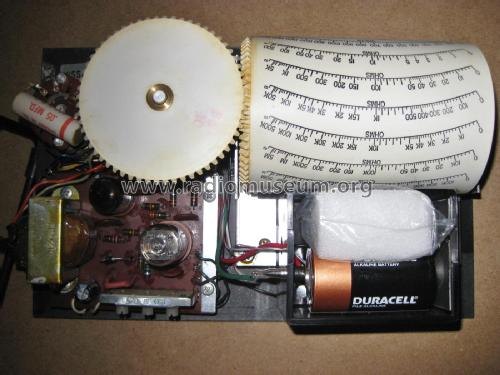
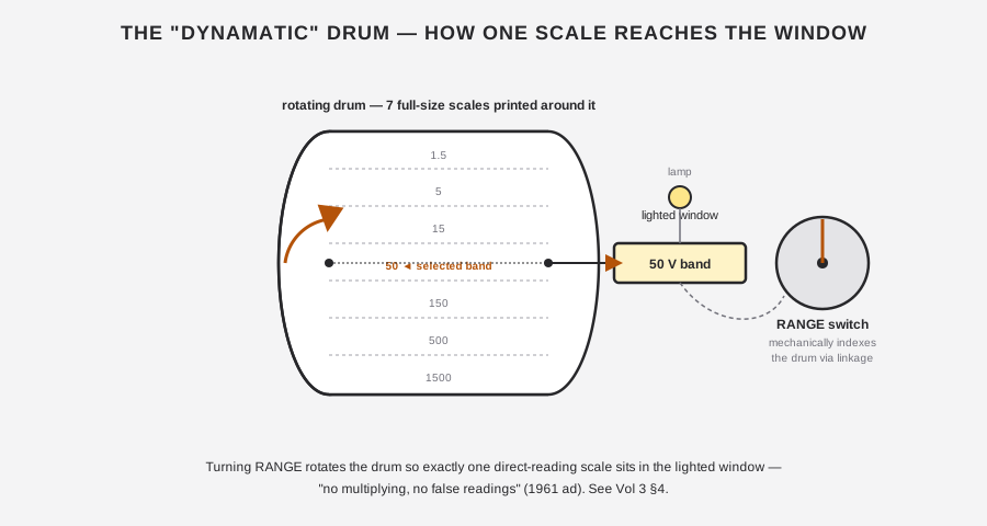
This is the feature the model name is built around, and it is the single most distinctive thing about opening the case. Where a conventional multi-range analog meter crowds several scales onto one printed card behind the pointer — DCV arcs stacked over ACV arcs stacked over an ohms arc, all sharing one pivot, forcing the user to find the right arc among several before reading it — the 375 gives every range its own individual, full-size, direct-reading scale printed around a rotating cylinder inside the case, and shows only one of them at a time through a lighted cutout window.
3.4.1 Why a Drum, Not a Multi-Scale Meter Face
The 1961 advertisement sells this feature hard, and the ad copy is worth quoting because it states the engineering rationale as plainly as any secondary source could:
“Individual Full-Size Scale for Each Range / Range Switch Automatically Sets Correct Scale / Only One Scale Visible at Any One Time / All Scales Are Direct Reading / No Multiplying — No False Readings.”
Translated: on a conventional crowded-face meter, a technician reading, say, the 50 V DC scale has to first find the correct arc among five or six overlapping printed scales, then read it — and a tired tech at the end of a long bench day misreading the 15 V arc as the 50 V arc (or vice versa) is a real and common failure mode with multi-scale meters. The Dynamatic drum removes that failure mode entirely: whatever scale is showing in the window is the range in use, full stop, because the RANGE switch and the drum are mechanically coupled. There is nothing to multiply, nothing to misread, and no adjacent arc to confuse it with.
3.4.2 Mechanical Indexing
The drum carries one scale per range for each of the ranged functions — seven bands for DC volts, seven for AC RMS, seven for AC peak-to-peak, three for DC current, seven for ohms — printed around its circumference (or across parallel drum sections; the exact internal partitioning between functions is not resolvable from the available photos, [UNCERTAIN]). The RANGE switch shaft couples mechanically to the drum through an indexing linkage, so rotating RANGE by one position advances the drum by exactly one scale-band’s worth of rotation, bringing the next range’s scale square into the window.
Note — this drum + indexing linkage is described by service-forum participants as unique to this instrument — not a shared part across the B&K line — which is exactly the kind of mechanism that becomes irreplaceable if physically damaged. Vol 5 treats this as the single highest-priority item to protect during any disassembly or transport of the unit. [LIKELY — forum]
3.4.3 Illumination
The window is lit — period listings describe the “cylinder” as lighting up, “making it easy on the eyes” [LIKELY — seller descriptions, consistent with the visible lamp near the window in the internals photo]. Illumination matters more on a drum-scale instrument than on a plain printed meter card, because the whole value proposition is a crisp, unambiguous read at a glance; a dim or burned-out lamp defeats the purpose even if the mechanism itself still indexes correctly. If a unit’s window looks dim, check the lamp before assuming a mechanical fault.
3.4.4 Refurb Implication (brief)
Because the drum is a one-of-a-kind mechanical assembly with no known replacement source, any internal work on a 375 should treat it as the fragile long-lead item on the chassis — full detail, including how to service around it safely, is in Vol 5.
3.5 Under the Hood — Tube Complement, Chassis & Power Supply
The 375 is a genuine vacuum-tube instrument. Its entire measuring path — from the input divider through to the meter deflection — runs through exactly two active devices, both common, cheap, and still readily available new-old-stock or as modern production: a 12AU7 dual triode and a 6AL5 dual diode. The power supply’s B+ comes from a selenium rectifier, not a tube rectifier and not a solid-state silicon diode. There is no transistor and no FET anywhere in the signal path — that architecture belongs to the later Model 277 “FET Multimeter” (~1972–1982), a different, later B&K instrument entirely (see Vol 1’s lineage discussion for the full family tree).
3.5.1 Tube Complement
Table 3 — Tube Complement
| Device | Role | Count |
|---|---|---|
| 12AU7 | Balanced-bridge DC amplifier — one triode section carries the measured/rectified signal, the other is the reference; the meter reads bridge unbalance between them | 1 |
| 6AL5 | AC rectifier — converts the AC input into a DC level the 12AU7 bridge can measure, supporting both the RMS and peak-to-peak AC functions | 1 |
| Selenium rectifier | B+ power supply rectification (not in the measuring signal path) | 1 |
3.5.1.1 12AU7 — Balanced-Bridge DC Amplifier
Every function on this instrument — DC volts, AC volts (via the 6AL5’s rectified output), and ohms (via the internal battery’s divider) — ultimately lands as a DC level at the 12AU7 bridge, which is the only thing actually driving the 100 µA meter movement. The bridge’s cathode-coupled configuration is what gives the instrument its high, range-independent input impedance — full circuit-theory treatment is Vol 2’s job, but for a hardware inventory it’s worth naming the actual part designators a service thread has documented inside the chassis: R21 (6.8 MΩ) from the 12AU7’s pin 2 grid to ground and R25 (3.3 MΩ) from pin 7, which in series form roughly the 10 MΩ internal divider that, added to the 1 MΩ probe resistor, produces the instrument’s headline 11 MΩ DC input. Balance/calibration trim is provided by R27 and R32 (11 kΩ each) and R30 (15 kΩ) [CONFIRMED — antiqueradios service thread; see Vol 5 for the refurbishing use of these values].
The 12AU7 is a standard 9-pin miniature (B9A) dual triode, identical in base and pinout to the tube used in countless audio preamps and other VTVMs of the period — useful to know when a spare is needed on short notice, since 12AU7 (and its close relatives 12AT7/12AX7, which differ in gain/plate resistance but share the base) remain in active production today for the guitar-amp and audio-hi-fi markets. The pin functions relevant to the bridge role documented above:
Table 4 — functions relevant to the bridge role documented above
| 12AU7 pin | Function | Role in the 375’s bridge |
|---|---|---|
| 1 | Plate, section 1 | Bridge arm 1 output |
| 2 | Grid, section 1 | Signal input (per antiqueradios: this is the R21 6.8 MΩ node) |
| 3 | Cathode, section 1 | Bridge arm 1 reference |
| 4, 5 | Heater | 6.3 V filament (center-tapped option not used in single-9-pin wiring) |
| 6 | Plate, section 2 | Bridge arm 2 output |
| 7 | Grid, section 2 | Reference/balance input (per antiqueradios: the R25 3.3 MΩ node) |
| 8 | Cathode, section 2 | Bridge arm 2 reference |
| 9 | Heater center tap | Filament center tap (if used) |
Note — this pinout table is generic 12AU7/ECC82 base data, not a 375-specific schematic transcription — it is included because it’s genuinely useful at the bench (tube swap, socket voltage checks) and because it gives the R21/R25 grid designators from the service-forum thread a physical pin to anchor to. The rest of the bridge’s resistor network (beyond R21/R25/R27/R30/R32) is Vol 2 / full-schematic territory, not reproduced here.
3.5.1.2 6AL5 — AC Rectifier
The 6AL5 dual diode rectifies the AC input signal so the resulting DC can be measured by the same 12AU7 bridge used for DC volts — there is no separate AC amplifier chain. This is the standard VTVM architecture: one precision DC-reading bridge, fed by whichever front-end (raw input, AC-rectified input, or ohms-battery-derived input) the SELECTOR has chosen [CONFIRMED tube role — service forum + schematic title block].
Unlike the 12AU7’s 9-pin Noval (B9A) base, the 6AL5 is a 7-pin miniature (B7G) tube — a smaller base with two fewer pins, not the same base family as the 12AU7 at all, so the two physically cannot share a socket:
Table 5 — socket
| 6AL5 pin | Function |
|---|---|
| 1 | Cathode, diode 1 |
| 2 | Plate, diode 2 |
| 3, 4 | Heater |
| 5 | Cathode, diode 2 |
| 6 | Internal shield |
| 7 | Plate, diode 1 |
Note — this pinout table is generic 6AL5 base data (RCA datasheet, JETEC base designation E7-1), not a 375-specific schematic transcription — included for the same bench-reference reasons as the 12AU7 table above (tube swap, socket voltage checks), not reproduced from the 375’s own schematic.
Like the 12AU7, the 6AL5 is a common, still-produced type shared with a huge range of period radio and TV service equipment — sourcing a replacement is not a practical concern the way sourcing a replacement drum assembly is (§4).
3.5.1.3 Selenium Rectifier — B+ Supply
Line power (117 V, 50–60 Hz) feeds a power transformer, whose secondary is rectified by a selenium rectifier to produce the tube stage’s B+. This is purely a power-supply component — it plays no role in the actual measurement path — but it is worth flagging on its own, because selenium rectifiers are a known vintage-gear hazard: a failing selenium stack can emit an acrid, genuinely unpleasant smell as the selenium coating degrades, and the material itself is best not handled bare-handed.
⚠ Danger — Selenium rectifiers and pre-1980 vintage electronics generally carry hazards this volume won’t repeat in full — see the shared
_shared/legal_ethics.mdfor the complete rundown (mains/isolation-transformer discipline, HV discharge, PCB-bearing transformers, and the selenium/asbestos/BeO/mercury-relay checklist for anything this old). Read it before opening the case for the first time.
3.5.2 Chassis Layout Tour
Beyond the drum assembly and its lamp, the internals photo set shows the expected complement for an instrument of this class and era: the power transformer, the selenium rectifier stack, the tube sockets for the 12AU7 and 6AL5, the precision ±1% multiplier/divider resistor string that the RANGE switch taps into, the ZERO/OHMS calibration pots, and — mounted in its own holder near the drum — the single 1.5 V D-size cell that powers the ohms function.
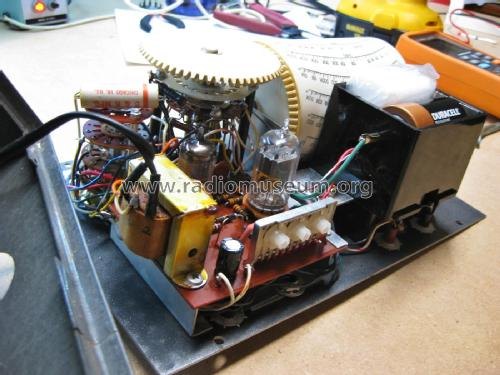
Table 6 — Chassis Layout Tour
| Chassis element | Notes |
|---|---|
| Power transformer | Steps line voltage for the B+ supply |
| Selenium rectifier | B+ rectification |
| 12AU7 socket + tube | Balanced-bridge DC amplifier |
| 6AL5 socket + tube | AC rectifier |
| Precision ±1% resistor string | Multiplier/divider network selected by RANGE |
| ZERO / OHMS pots (R27, R32, R30) | Bridge balance + ohms full-scale trim |
| 1.5 V D-cell + holder | Ohms function excitation source only |
| Drum + indexing linkage | The Dynamatic mechanism (§4) |
The battery deserves a specific note here even though its refurb implications belong to Vol 5: it powers ohms only — positive terminal routes to the “E” deck of the function switch (documented as switch terminal 12), negative to circuit ground — and it plays no role whatsoever in DC volts, AC volts, or DC current measurement [CONFIRMED — antiqueradios thread]. A dead cell therefore takes out ohms and nothing else; if DC/AC volts still read correctly but ohms is dead or won’t zero, the battery (or its holder contacts) is the first thing to check, not the tube complement.
3.5.3 Construction Style
Like essentially every American tube-era test instrument of this size and price point, the 375’s internal wiring is point-to-point rather than printed-circuit — components mounted directly to terminal strips, tube sockets, and switch-deck lugs, connected by hand-formed and hand-soldered wire runs rather than a PCB. This has two practical consequences for anyone servicing the unit decades later: first, every connection is visually traceable and individually resolderable without a PCB’s layered copper to fight; second, and less helpfully, there is no silkscreened reference designator printed next to each part the way a PCB assembly would carry, so identifying “R21” or “R25” on the actual chassis means cross-referencing wire color, lug position, and the schematic together rather than reading a label off the board. [LIKELY — inferred from era/class/price point and consistent with the internals photos; not an explicit manual statement]
3.6 The Meter Movement
3.6.1 Sensitivity & Type
The panel meter is a 100 microampere full-scale movement [CONFIRMED — ad]. That sensitivity number is what the entire bridge circuit is built around: the 12AU7 bridge’s unbalance current at full input never has to swing more than 100 µA to deflect the pointer full scale, which is a genuinely small, easily-perturbed current — one more reason the ZERO pot’s grounding integrity (§3.3, §7 refurb note) matters as much as it does.
Whether the movement itself is a taut-band suspension or a conventional jeweled-pivot D’Arsonval is [UNCERTAIN]. Neither the 1961 ad nor the radiomuseum listing states “taut-band” anywhere in the verified text, and a 100 µA movement of this class and era is, if anything, more likely to be a conventional jeweled-pivot design than a taut-band one — taut-band suspensions were a somewhat later and initially higher-end refinement. Treat any claim that the 375 uses a taut-band movement as an unverified assumption, not a fact — this is a point on which the project’s own older scaffold notes guessed wrong, and this volume corrects that guess rather than repeating it.
3.6.2 Mirror Scale & Knife-Edge Pointer
The meter uses an anti-parallax mirrored scale paired with an iridescent knife-edge pointer [CONFIRMED — ad]. The mirror strip runs along the scale arc; the reading technique is the same one used on essentially every quality analog meter of the era (and on the sibling Simpson 311‑2 and Simpson 260 — see those dives for the identical technique): align the pointer with its own mirror-reflected image so no reflection is visible off to one side, and only then read the scale under the now-superimposed pointer tip. Skipping this step and reading the pointer “on the diagonal” introduces exactly the kind of parallax error that a mirror scale exists to eliminate.
3.6.3 Accuracy
The precision multiplier/divider resistors that set every range are specified at ±1% [CONFIRMED — ad]. The instrument’s overall stated accuracy figure, however, is [UNCERTAIN] — the relevant line in the only located copy of the 1961 ad spec block is partially obscured by a watermark. Typical VTVMs of this era and class quote roughly ±3% of full scale on DC and ±5% on AC, and those figures are a reasonable planning assumption, but they should not be quoted as this instrument’s verified spec until a clean copy of the ad or the gated service manual (Vol 5) resolves the obscured text.
3.7 The Range Set
The full range table below is transcribed directly from the 1961 advertisement’s spec block — the single primary source for every number in it.
Table 7 — The Range Set
| Function | Ranges (full scale) | Number of ranges |
|---|---|---|
| DC Volts | 1.5, 5, 15, 50, 150, 500, 1500 V | 7 |
| AC Volts (RMS) | 1.5, 5, 15, 50, 150, 500, 1500 V | 7 |
| AC Volts (peak-to-peak) | 1.5, 5, 15, 50, 150, 500, 1500 V | 7 |
| DC Current | 5 mA, 50 mA, 500 mA | 3 |
| Ohms | 500 Ω, 5 kΩ, 50 kΩ, 500 kΩ, 5 MΩ, 50 MΩ, 1000 MΩ | 7 |
That is 31 total ranges across five functions, every one of them with its own dedicated drum scale (§4) rather than a shared multiplied arc — 31 individual printed scales wrapped around one rotating cylinder, which puts the physical scope of the Dynamatic mechanism in perspective.
3.7.1 DC Volts / AC Volts RMS / AC Volts Peak-to-Peak
All three voltage functions share the identical 1.5 – 5 – 15 – 50 – 150 – 500 – 1500 V cascade — a roughly ×3.3, then ×3, then ×3.3, then ×3, then ×3.3, then ×3 progression, the standard “1-3-… in decades” spacing that keeps every practical bench voltage within a comfortable fraction of full scale on some range. Because DC+, DC−, AC RMS, and AC P-P are each their own SELECTOR position, the same seven numeric range values recur across four SELECTOR settings, drawing on what is most likely three drum scale sets rather than four — DC+ and DC− appear to share a single DC scale set (§8), while AC RMS and AC P-P each get their own; as noted in §4.2, the drum’s exact internal band partitioning by function isn’t resolvable from the available photos, so treat the DC+/DC− sharing as [UNCERTAIN] rather than confirmed. Whichever way the drum is actually partitioned, the underlying point stands: on a crowded conventional meter face, cramming DC and two flavors of AC onto shared arcs (as many contemporaries did, distinguishing them only by a small “AC” or “DC” label at the arc’s end) is a classic source of a tired technician reading the wrong curve. This instrument doesn’t offer that opportunity.
Note — RMS and peak-to-peak are genuinely different quantities on a non-sinusoidal waveform (which is most of what a service tech encounters mid-repair — clipped audio, sync pulses, ripple). Having both as first-class SELECTOR/scale combinations, rather than one AC range with a hand-applied ×2.83 or ×0.707 conversion factor, is a real usability advantage worth noting when comparing this instrument to the Simpson 311‑2’s own AC provisions.
3.7.2 DC Current — the Unusual Extra
Most VTVMs of this class are strictly volts-and-ohms instruments; DC current is left to a separate milliammeter or to a general-purpose VOM like the Simpson 260. The 375 breaks from that convention and includes three built-in DC current ranges — 5 mA, 50 mA, and 500 mA — fed through their own dedicated jack pair (§3.4) rather than the shared voltage/ohms input jack. The 1961 ad calls this out explicitly: “Includes DC Current Ranges, too” [CONFIRMED].
The practical implication: unlike every other function on this instrument, DC current measurement means breaking the circuit under test and inserting the meter in series — not bridging a high-impedance probe across a node, which is what the 11 MΩ input divider is built for on every other function. A technician reaching for the 375 to check plate current or heater current doesn’t need to dig out a separate milliammeter; Vol 4 covers the operating-procedure difference between the in-series current connection and the bridging voltage/ohms connection in detail, because getting that distinction backward on a live circuit is a real way to either blow a fuse/resistor in the meter or open the circuit unexpectedly.
In practical tube-circuit service work, the three current ranges cover the currents an engineer actually chases inside a receiver or amplifier chassis: 5 mA comfortably spans small-signal stage cathode or screen currents; 50 mA covers a typical output-stage plate or cathode current; 500 mA reaches heater/filament string currents on series-string AC/DC sets, where a whole tube chain shares one current path and a single open heater kills the entire string. Having all three built into the same instrument that already lives on the bench for voltage and resistance checks removes a genuine friction point — swapping to a second dedicated milliammeter mid-troubleshoot, re-zeroing it, and then swapping back — that a volts-and-ohms-only VTVM imposes.
3.7.3 Ohms
The ohms cascade — 500 Ω, 5 kΩ, 50 kΩ, 500 kΩ, 5 MΩ, 50 MΩ, 1000 MΩ — spans six decades on seven ranges, topping out at 1000 megohms (1 gigohm), an unusually high ceiling for a battery-powered 1.5 V ohms source of this era. The full circuit description (how a 1.5 V cell drives a divider that the 12AU7 bridge reads as resistance) is Vol 2’s job; the hardware-relevant fact for this volume is that the entire ohms function runs off the single internal 1.5 V D-cell described in §5’s chassis tour — there is no separate high-voltage ohms supply, and the top-range ceiling is a function of the divider network’s design, not of any second battery or booster circuit.
3.7.4 Design Rationale — Why 11 MΩ and This Range Cascade
The 11 MΩ DC input figure is not an arbitrary round number; it is the era’s standard VTVM answer to a specific design tension. A voltmeter’s input resistance has to be high enough that connecting it to a high-impedance node (a grid-bias divider, an AVC line, a screen-dropping-resistor tap) doesn’t visibly sag that node’s voltage — the same loading problem that makes a 20 kΩ/V VOM unsuitable for those same nodes (see the Simpson 260 Series 8 comparison, and Vol 6’s full discussion). But it also can’t be made arbitrarily high without cost and stability tradeoffs in the divider network and the bridge’s own input capacitance. 1 MΩ in the probe tip + 10 MΩ inside the chassis = 11 MΩ was the practical balance the era converged on across essentially the whole VTVM category — B&K’s own later 177 keeps the same 12AU7/6AL5 bridge topology (its spec sheet actually quotes a higher ~20 MΩ DC / ~11 MΩ AC, not the same 11 MΩ DC figure — do not read the two instruments as sharing an input-resistance spec, only the bridge architecture), and the design pattern recurs on the sibling Simpson 311‑2 (per that instrument’s own Vol 2/3). Building the probe’s 1 MΩ resistor into the tip rather than inside the chassis also isolates stray input capacitance and lead inductance from the sensitive node under test — a detail that matters more on RF work (Vol 4) than on DC bench voltage checks, but which the same probe geometry (§3.4) serves in both cases.
The 1‑3 decade range cascade (1.5 → 5 → 15 → 50 → 150 → 500 → 1500) is likewise not unique to this instrument — it’s the standard analog-meter range spacing that keeps any practical voltage within roughly a 3:1 to 10:1 span of some range’s full scale, so the needle deflection stays in the accurate, easy-to-read upper two-thirds of an arc rather than pinned near zero (where percentage reading error is worst) on an oversized range. What is specific to this instrument is applying that same seven-step cascade identically across DC, AC RMS, and AC peak-to-peak (§7.1) — and giving each of those 21 range/function combinations, plus the 3 current ranges and 7 ohms ranges, its own individual drum scale rather than sharing arcs. That multiplication of individual scales (31 in total, §7) is the direct consequence of the design decision documented in §4 — and is very likely why the drum, rather than a conventional multi-scale card, became necessary at all once B&K committed to this many discrete functions and ranges on one dial.
3.8 Cross-Reference: SELECTOR / RANGE / Scale-Window Map
The table below ties together everything above into the sequence an operator actually walks through: choose a function on SELECTOR, choose a range on RANGE, and read whichever scale the drum has brought into the window.
Table 8 — Cross-Reference: SELECTOR / RANGE / Scale-Window Map
| SELECTOR position | RANGE choices (7 unless noted) | What the window shows |
|---|---|---|
| AC P-P | 1.5 / 5 / 15 / 50 / 150 / 500 / 1500 V | Peak-to-peak AC scale for the chosen range |
| AC RMS | 1.5 / 5 / 15 / 50 / 150 / 500 / 1500 V | RMS AC scale for the chosen range |
| DC+ | 1.5 / 5 / 15 / 50 / 150 / 500 / 1500 V | DC scale for the chosen range, positive polarity |
| DC− | 1.5 / 5 / 15 / 50 / 150 / 500 / 1500 V | DC scale for the chosen range, negative polarity |
| OHMS | 500 Ω / 5 k / 50 k / 500 k / 5 M / 50 M / 1000 MΩ (7) | Ohms scale for the chosen range (back-reading, per §6 of Vol 2) |
| DC MA | 5 / 50 / 500 mA (3) | DC current scale for the chosen range |
| OFF | — | Window dark, instrument de-energized |
This is the practical payoff of the Dynamatic drum: 31 numeric ranges across five functions, and at any given moment the operator sees exactly one scale — never a search through overlapping arcs, never a multiplier to apply by hand.
3.9 Comparison Context — the Two-VTVM Bench
Jeff keeps this 375 next to a Simpson 311‑2 VTVM as a deliberate cross-check pair — two independently-designed high-impedance voltmeters on the same bench, so a reading that looks wrong can be checked against a second instrument built on a different bridge/rectifier implementation before blaming the circuit under test rather than the meter. Where the 375’s Dynamatic drum trades mechanical complexity for an unambiguous single-scale read, the 311‑2 takes a different hardware approach entirely (see that instrument’s own Vol 3 for its panel and internals). Both instruments earn their keep over the Simpson 260 Series 8 VOM on any high-impedance node — a 20 kΩ/V VOM on its most sensitive range still only presents a few megohms of loading, more than enough to visibly sag a grid-bias or AVC line, where this instrument’s 11 MΩ input (§4 of Vol 2, referenced from the hardware described here) does not. Vol 6 draws out the full side-by-side comparison and decision matrix across all three instruments.
The hardware picture in this volume also explains why a two-VTVM bench is worth the shelf space in the first place, beyond simple redundancy. Two instruments built on genuinely different bridge and rectifier implementations are unlikely to share a systematic error in the same direction on the same measurement — if this instrument’s 12AU7 bridge has drifted slightly out of calibration in a way that reads a shade high, that drift has no reason to correlate with whatever the 311‑2’s own front end happens to be doing that day. A reading that agrees between the two is a much stronger piece of evidence than a reading from either instrument alone; a reading that disagrees is the signal to stop and recalibrate (Vol 5) before trusting either one on a critical measurement. That is the practical payoff of keeping this instrument’s hardware — tube complement, bridge topology, drum mechanism, and all — genuinely distinct from its bench neighbor rather than simply owning two of the same meter.
3.10 What This Volume Could Not Verify
Working from a 65-year-old instrument whose full 24-page service manual sits behind two token-gated download hosts (BAMA and elektrotanya — see Vol 5 for the specific access failure) means this volume carries a handful of open items rather than invented numbers. Collected here in one place, so a future session with browser access to either gated manual knows exactly what to go resolve:
Table 9 — session with browser access to either gated manual knows exactly what to go resolve
| Open item | Status | Where it matters |
|---|---|---|
| Movement suspension type (taut-band vs jeweled-pivot) | [UNCERTAIN] — treat as jeweled-pivot unless proven otherwise | §6.1 |
| Overall stated accuracy (% of full scale, DC and AC) | [UNCERTAIN] — obscured by watermark in the only located ad copy | §6.3 |
| dB scale presence | [NOT FOUND] — working assumption is “none” | §3.1 |
| AC input impedance as a stated 375-specific number | [NOT FOUND] — do not borrow the 177’s ~11 MΩ AC figure | Vol 2 cross-ref |
| Exact internal partitioning of scale bands around the drum by function | [UNCERTAIN] — photos don’t resolve the internal layout | §4.2 |
| AE-1A/PR-38 exact bandwidth spec (vs. the AV-1A-class 250 MHz figure) | [UNCERTAIN] | §3’s RF probe subsection |
| Warm-up time to stable zero | [NOT FOUND] — no specific duration published | Vol 4 |
| Overall published accuracy tolerance in the service manual (vs. the ad’s ±1% resistor spec) | [UNCERTAIN] — manual not directly read | §6.3 |
None of these gaps change the headline specs this dive relies on (11 MΩ DC input, 100 µA movement, the 31-range set, the 12AU7/6AL5/selenium complement) — all of those are [CONFIRMED] against the primary ad and schematic sources. The gaps are the second-order numbers a full manual would supply and a photograph-plus-forum-thread reconstruction cannot.
Sources
- radiomuseum.org — B&K Dynamatic 375 (year, tubes, selenium B+, price, size, schematic + photo set): https://www.radiomuseum.org/r/dynascan_k_dynamatic_375.html
- radiomuseum.org — 1961 advertisement spec block (ranges, 11 MΩ, 100 µA movement, 1½ V battery, ±1% multipliers, size/price): https://www.radiomuseum.org/images/radio/b_k_dynascan_corp/b_k_dynamatic_375_2105857.jpg
- radiomuseum.org — schematic image (title block “B&K MFG CO MODEL 375 VTVM,” drawing no. PM-285M-F): https://www.radiomuseum.org/images/schematic-medium/b_k_dynascan_corp/b_k_dynamatic_375_2095388.png
- radiomuseum.org — front-panel and internals photo set: https://www.radiomuseum.org/images/radio/dynascan_corporation/b_k_dynamatic_375_1058470.jpg and https://www.radiomuseum.org/images/radio/b_k_dynascan_corp/b_k_dynamatic_375_2095383.jpg
- BAMA manual archive — B&K 375 (
bk375.djvu, includes AE-1A & PR-38 RF probe pages and the 1961 ad; JS/cloud-gated at time of research): http://bama.edebris.com/manuals/b&k/375 - elektrotanya — “B-K DYNAMATIC-375 TUBE VOLTMETER” service manual, 24 pp PDF (token-gated at time of research): https://elektrotanya.com/b-k_dynamatic-375_tube_voltmeter.pdf/download.html
- elektrotanya — “BK PRECISION DYNAMATIC 375 VTVM INCLUDING THE AE-1A AND PR-38 RF PROBES” (djvu): https://elektrotanya.com/bk_precision_dynamatic_375_vtvm_including_the_ae-1a_and_pr-38_rf_probes.djvu/download.html
- Antique Radio Forums — “B&K Dynamatic 375 VTVM woes” (grounding fix; R21 6.8 MΩ / R25 3.3 MΩ / R27, R32 11 kΩ / R30 15 kΩ; battery routed to function-switch “E” deck terminal 12; confirms 12AU7 + 6AL5 tube roles): https://antiqueradios.com/forums/viewtopic.php?p=1517272, https://antiqueradios.com/forums/viewtopic.php?p=1517468, https://www.antiqueradios.com/forums/viewtopic.php?t=3786
- Surplus Sales of Nebraska — B&K RF Demodulator Probe (AV-1A class, “to 250 MHz, for most VTVMs”): https://www.surplussales.com/items/99536/bk-rf-demodulator-probe/
- radiomuseum.org — B&K 177 VTVM (~1970, same 12AU7 + 6AL5 complement, battery-less ohms — the direct successor referenced for family context): https://www.radiomuseum.org/r/dynascan_precision_model_vtvm_177.html
- elektrotanya — B&K 277 solid-state FET multimeter, 1982 instruction/service manual (confirms the 277 is the later, unrelated FET-input model): https://elektrotanya.com/bk-precision_277_sollid_state_electronic_multimeter_1982_instr._sm.zip/download.html