B&K Dynamic 375 VTVM · Volume 4
B&K Dynamatic 375 — Vol 4: Using It — Operating Procedure, Probes & Safety
Warm it up, zero it twice, then trust the drum — a working procedure for the bench, not the museum case.
4.1 Scope of This Volume {-}
Vol 1 explained why a VTVM earns bench space, Vol 2 walked the 12AU7 balanced-bridge/6AL5 rectifier/ohms circuit theory, and Vol 3 mapped every control on the front panel. This volume is the procedure — what to actually do, in order, to get a trustworthy reading out of the Dynamatic 375, plus the probe accessories and the safety discipline that go with a mains-powered, tube-heater, metal-case instrument built in 1961.
Read this volume with the instrument in front of you. Where a step assumes you already know what a control is (ZERO, OHMS, the RANGE/SELECTOR pair, the DC CURRENT jacks), that control is described in full in Vol 3 §3; this volume only re-describes a control when the procedure needs the reminder.
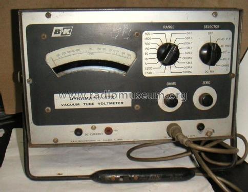
Note — This is the same control-panel photograph used in Vol 1 and Vol 3; it is not re-shot here. Refer back to Vol 3 §3 for a control-by-control breakdown if a name below (SELECTOR, RANGE, OHMS, ZERO, DC CURRENT jacks) is unfamiliar.
4.2 Power-On and Warm-Up
4.2.1 Why a tube VTVM cannot be trusted cold
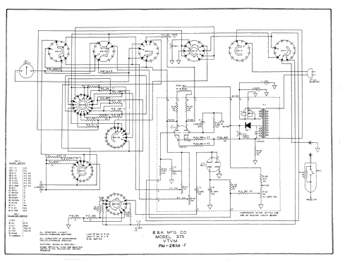
The 375’s measuring path is a 12AU7 dual-triode balanced bridge (Vol 2 §2): one triode carries the signal, the other is the reference, and the 100 µA meter reads the unbalance between the two halves. Both triode sections share one glass envelope and one heater, so they warm together — but “together” is not “instantly,” and a cathode-coupled bridge is only as good as the thermal symmetry of its two halves. As the tube heats from a cold start, cathode emission, plate current, and the DC operating point of both sections all drift before settling to a stable equilibrium. Selenium-rectified B+ (Vol 2 §6) also has its own small warm-up creep. The net effect on the meter is the same symptom every tube-instrument tech knows: the zero point walks for the first several minutes after power-up, then holds.
Note — The exact 375 warm-up time is [NOT FOUND] in the surviving documentation. Do not treat any specific “wait N minutes” figure below as a manufacturer spec — it is standard tube-VTVM practice, not a 375-specific number. In practice: power up, do something else on the bench for a few minutes, then re-check zero (§2) before trusting a critical reading. If the pointer is still visibly creeping, it isn’t warmed up yet.
4.2.2 Power-on sequence
Table 1 — Power-on sequence
| Step | Action | Why |
|---|---|---|
| 1 | Set SELECTOR to OFF before plugging in. | Don’t energize the bridge/rectifier chain mid-transient with the function switch in an unknown state. |
| 2 | Inspect the line cord and, if it has one, the ground pin (§8.1) before every session, not just the first. | A cracked cord or a defeated ground pin is one of the most common vintage-gear safety failures. |
| 3 | If the cord is grounded, plug into a grounded outlet — never a cheater plug or a 2-to-3 adapter with the ground tab floating. | Where a ground pin exists on this instrument, it is not optional; see §8.1 for why cord type shouldn’t be assumed. |
| 4 | Rotate SELECTOR off OFF into any DC or AC position. Pilot/scale illumination should light the drum window. | Confirms the transformer/rectifier chain and the drum lamp are alive before you invest warm-up time. |
| 5 | Let the instrument sit idle, unloaded, probes not yet connected to a circuit, for several minutes. | This is the warm-up window — see above. |
| 6 | Proceed to mechanical zero check, then electrical ZERO ADJUST (§2), after warm-up, not before. | Zeroing a cold bridge just means re-zeroing again once it drifts. |
4.2.3 Re-warm-up discipline
Treat warm-up as a per-session ritual, not a one-time event:
- If the 375 has been off for more than a few minutes, warm it up again before trusting a precision reading. Tube cathodes cool quickly.
- A quick spot-check (“is this rail roughly 12 V or roughly 0 V?”) doesn’t need a full warm-up. A calibration-grade reading you’re about to write into a log does.
- On a long bench session, periodically glance at zero with the probes shorted (§2.2) — thermal drift in the room, or the 12AU7 continuing to age through the session, can walk the bridge slowly even after the initial warm-up settles.
4.3 Zeroing — Mechanical, Then Electrical
Zeroing is a two-stage process, and the two stages are not interchangeable. Skipping either one, or doing them out of order, is the single most common way to get a plausible-looking but wrong reading out of any VTVM.
4.3.1 Mechanical zero (power off)
This is the ordinary D’Arsonval-movement mechanical zero, identical in principle to any analog meter:
- With the instrument unpowered (or at minimum with no signal applied and the SELECTOR at OFF), look at the meter pointer at rest.
- It should sit exactly on the left-hand zero mark of the scale window with zero current flowing through the movement — no bridge balance involved yet, purely mechanical spring tension.
- If it doesn’t, use the small mechanical zero-adjust screw at the base of the meter movement (below the scale bezel) to walk the pointer onto the mechanical zero mark. A jeweler’s screwdriver, small adjustments, patience.
Note — The movement type is [UNCERTAIN]: the ad and radiomuseum listing never say “taut-band,” and a 100 µA 1961 movement of this class is more likely a conventional jeweled-pivot D’Arsonval than a taut-band design (Vol 3 §4 has the full discussion). This matters here because jeweled-pivot movements are the ones that need — and drift out of — mechanical zero from ordinary bench knocks and gravity-orientation changes; a taut-band movement is comparatively immune. Check mechanical zero whenever the instrument has been jostled, dropped, shipped, or laid on its back for a while, not just once at acquisition.
4.3.2 Electrical ZERO ADJUST (power on, warmed up)
This is the bridge-balance step, and it is specific to the VTVM’s active circuit — it has nothing to do with the mechanical spring.
- Warm up the instrument fully (§1).
- Set SELECTOR to a DC position (DC+ or DC−).
- Short the probe tip to the COMMON/ground lead — touch them together, or clip them to the same point — so the DC input sees exactly 0 V.
- The meter should read exactly 0 on the DC scale. If it doesn’t, adjust the front-panel ZERO control until it does.
- What ZERO is actually doing: it balances the two triode sections of the 12AU7 bridge so that, with no differential signal at the grid, the two cathode/plate branches produce no net current through the 100 µA movement (Vol 2 §2). It is nulling the bridge, not moving a spring.
⚠ Danger — Never confuse “shorting the probe to ground for a zero check” with “assuming the input is safe to touch.” Do the short with the leads only, not by bridging with a finger, and only after confirming the SELECTOR is on a DC (not OHMS, not AC, not RF) function so you know exactly what’s being nulled.
4.3.3 When to re-zero
Table 2 — When to re-zero
| Trigger | Re-zero? |
|---|---|
| Every session, after warm-up, before the first critical reading | Yes — always |
| Switching between DC+ and DC− | Recommended — the bridge’s two halves are not perfectly symmetric; a fresh null on the polarity you’re about to use costs seconds |
| Mid-session, every 20–30 minutes on a long job | Good practice — the 12AU7 keeps drifting slowly as it ages through the session and the room temperature shifts |
| After any probe or lead change | Yes — different lead capacitance/resistance can nudge the null slightly |
| As the tube ages across months/years of ownership | Yes, and if the pointer won’t null to zero at all anymore, that’s the failure mode described in Vol 5 (bridge balance drift / 12AU7 wearing out) |
Zeroing is cheap — it costs fifteen seconds and a probe-tip touch. Skipping it costs you a reading you can’t trust and won’t know it.
4.4 Measuring DC Volts
4.4.1 The probe body — one tip, switched for three functions
Before working through DC procedure, it’s worth understanding what’s physically inside the single DC-AC-Ohms probe supplied with the instrument, because the same probe body serves DC, AC, and ohms, and it does not do so passively.
The 1 MΩ series resistor that gives the DC path its isolation (and, combined with the meter’s internal 10 MΩ divider, its 11 MΩ total input resistance — §3.4 below) physically lives in the probe tip itself, not in the meter chassis. That’s a deliberate era-standard VTVM layout choice: putting the isolation resistor at the tip, right at the point of contact, keeps stray capacitance in the connecting cable from forming a low-pass filter ahead of the resistor, which would otherwise round off fast DC transitions and bleed AC response.
The catch is that a 1 MΩ resistor sitting in series with every function would be wrong for AC and wrong for ohms — an extra 1 MΩ ahead of the 6AL5 rectifier would badly attenuate an AC signal on the lower ranges, and an extra 1 MΩ ahead of the ohms bridge would swamp any resistance reading below the megohm range. Per the standard B&K/era probe design for this instrument class, the function switch itself routes that 1 MΩ resistor into or out of the circuit: it stays in-circuit for DC, and is switched out (effectively shorted) for AC and Ohms [LIKELY — by analogy to sibling B&K probe designs of the same era (per byan-roper.org’s switchable-VTVM-probes writeup); not independently re-verified against the 375’s own schematic in the sources available to this dive]. Practically, this means:
- The same physical probe and cable serve DC, AC, and Ohms — there is nothing to swap for those three functions, only the SELECTOR position.
- The 11 MΩ input figure is a DC-only number. The AC input impedance for this specific model is [NOT FOUND] — don’t assume the AC path also presents 11 MΩ; the 1 MΩ tip resistor isn’t in that path the same way.
- Swapping to the RF demodulator probe (§7) is a genuine physical probe swap, not a function-switch reconfiguration of the same probe — it’s a different accessory entirely, purpose-built for the frequencies where the standard probe’s cable capacitance would otherwise dominate.
4.4.2 DC+ vs. DC−
The SELECTOR offers separate DC+ and DC− positions rather than a single DC position you reverse leads on. This is a manual polarity-reversal feature [LIKELY, per the 1961 ad’s spec block]: pick DC+ to read a node that’s positive with respect to your ground lead, DC− to read one that’s negative, without moving the probe or ground clip. This matters constantly in tube-circuit work — grid-bias voltages, AVC lines, and cathode-bias points are frequently negative with respect to chassis, and being able to flip the meter’s internal sense rather than swap physical leads is faster and safer (you’re not disconnecting and reconnecting a ground clip near a hot chassis mid-measurement).
Procedure:
- Estimate (or know from the schematic) whether the point you’re probing is positive or negative relative to your ground/common connection.
- Set SELECTOR to DC+ or DC− accordingly.
- If the pointer tries to swing hard left off-scale, you guessed the wrong polarity — flip to the other DC position rather than reversing the physical leads.
4.4.3 Range selection and the drum scale
- Start on the highest DC range (1500 V) if you have no idea what the node’s voltage roughly is. Step down through 500, 150, 50, 15, 5, 1.5 V until the pointer sits usefully on-scale. This is the same “start high, work down” discipline as any multi-range analog meter — it protects both the movement and your eyes from a full-scale slam.
- Turning RANGE does double duty on this instrument: it selects the attenuator tap and mechanically rotates the correct full-size scale into the lighted drum window (the “Dynamatic” feature — Vol 2 §1, Vol 3 §2). You should never be reading a scale meant for a different range; the drum indexes automatically, which is the entire point of the mechanism. If the visible scale’s numbering doesn’t match the RANGE knob’s position, something is mechanically wrong with the drum linkage — see Vol 5.
- Read the pointer against the scale now sitting in the window. Every range gets its own full-width printed scale rather than sharing one crowded multi-scale face, so there is no mental “×10, move the decimal” step at read time (the RANGE selection has already done that work by rotating in the correct printed numbers). [CONFIRMED — 1961 ad: “All Scales Are Direct Reading — No Multiplying — No False Readings”]
Note — This direct-reading drum is the 375’s whole reason for being distinctive against ordinary multi-scale VTVMs of its era, and it’s also its most mechanically fragile part. Read the scale, don’t force the RANGE knob if it feels like it’s binding against the drum’s indexing stops — see the DON’Ts table in §9.
4.4.4 DC loading error — why 11 MΩ matters, worked example
Every voltmeter loads the circuit it measures by some finite input resistance. The question is never “is
there loading,” it’s “how much, and does it matter.” The Dynamatic 375 holds 11 MΩ on every DC range
[CONFIRMED — 1 MΩ probe-tip resistor + 10 MΩ internal divider, per the 1961 ad’s stated 11 MΩ input spec], which is constant across
all ranges — unlike a loadable analog VOM, where input resistance is (sensitivity in Ω/V) × (range voltage) and shrinks dramatically on low ranges.
For comparison, the shop’s Simpson 260 VOM is 20 kΩ/V on DC (per its own CLAUDE.md) — meaning its input resistance on a given range equals 20,000 Ω multiplied by that range’s full-scale voltage. On a 2.5 V range that’s only 50 kΩ; even on a 250 V range it’s 5 MΩ, still less than half the 375’s constant 11 MΩ.
The loading-error formula for a voltage divider being probed is straightforward:
% error (reading low) = Rsource / (Rsource + Rmeter) × 100where Rsource is the Thévenin source resistance the node presents (e.g. the parallel combination of the
bias resistors feeding it).
Table 3 — DC loading error — why 11 MΩ matters, worked example
| Source resistance at the node | 375 error (11 MΩ) | Simpson 260 error on its best-case 250 V/5 MΩ range | Simpson 260 error on a 2.5 V/50 kΩ range |
|---|---|---|---|
| 100 kΩ | 0.9 % | 2.0 % | 66.7 % |
| 1 MΩ | 8.3 % | 16.7 % | 95.2 % |
| 5 MΩ | 31.3 % | 50.0 % | ~99.0 % |
The pattern that matters: on a genuinely high-Z node (a grid-bias divider or AVC line commonly presents source resistances in the hundreds of kΩ to several MΩ), the loadable VOM’s error isn’t a rounding nuisance, it’s a wrong answer — and it gets worse, not better, the more you need precision (a low-range, low-voltage measurement on the VOM is exactly where its input resistance collapses). The 375’s constant 11 MΩ keeps the error in the low single digits across that same range of source resistances. This is the entire reason a VTVM exists as an instrument class (Vol 1 §1) and it’s why Jeff keeps the Simpson 260 VOM (see its CLAUDE.md) for power rails and filament circuits — low source impedance, loading is trivial, the VOM’s speed and no-warm-up convenience win — and reaches for the 375 (or its bench-mate, the Simpson 311-2 VTVM) whenever the node is grid, screen, AVC, or anything else fed through a large resistor. Vol 6 covers the full two-VTVM cross-check bench workflow.
4.5 Measuring AC Volts
4.5.1 RMS vs. peak-to-peak — two separate range sets, not a math trick
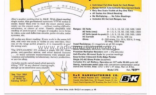
The 375 gives you two independent AC function positions — AC RMS and AC P-P — each with its own full seven-range cascade (1.5/5/15/50/150/500/1500 V) [CONFIRMED, 1961 ad spec block]. This is a materially different design choice from a VTVM that only reads peak (or average) and expects you to hand-calculate an RMS-equivalent. Both AC functions share the same 6AL5 dual-diode rectifier ahead of the 12AU7 bridge (Vol 2 §3); the AC RMS position is calibrated assuming a sine-wave input — its scale markings are meaningful RMS numbers only for a sine, because a rectifier-and-meter AC voltmeter of this era reads some rectified average or peak quantity and the scale is printed assuming a fixed sine-derived crest/form factor. The AC P-P position instead gives you the peak-to-peak swing directly, useful when the waveform genuinely isn’t sinusoidal, or when peak-to-peak swing is the number you actually need (checking a sync pulse amplitude, a clipping threshold, an oscillator’s drive level).
4.5.2 Waveform caveats
⚠ Danger — Reading a square wave, a sawtooth, ripple with harmonic content, or any other non-sine waveform on the AC RMS position will give you a number that looks like a calibrated RMS reading but isn’t one — the scale’s calibration constant assumes a sine crest factor. If you know or suspect the waveform isn’t a sine (line-frequency ripple riding on DC, an audio signal with heavy distortion, a switching waveform), use AC P-P instead and interpret the peak-to-peak number directly, or better, put it on a scope.
Practical rule of thumb for this bench: use AC RMS confidently for line voltage, transformer secondaries, and clean sine test-tone work; treat any AC RMS reading on a circuit you haven’t scoped as an estimate, not a precision figure, until you’ve confirmed the waveform shape some other way.
Common tube-bench signals and which AC function actually fits them:
Table 4 — Common tube-bench signals and which AC function actually fits them
| Signal | Waveform | Function to use |
|---|---|---|
| Transformer secondary, line-derived | Sine | AC RMS — calibration assumption holds |
| Clean audio test tone from a sine generator | Sine | AC RMS |
| Power-supply ripple riding on a DC rail | Sawtooth-like, non-sine | AC P-P (or better, scope it — a VTVM AC reading of raw ripple is a rough estimate at best) |
| Sync pulses / blanking pulses (TV/video service work) | Pulse, sharply non-sine | AC P-P — the whole point is the peak swing, not an RMS-equivalent |
| Audio signal with visible distortion/clipping | Distorted sine | AC P-P if precision matters; AC RMS only as a rough relative indicator |
| RF/IF carrier | Sine, but at a frequency the AC rectifier isn’t rated for | Neither — use the RF demodulator probe instead (§7) |
That last row is worth flagging on its own: the AC RMS/P-P functions run through the 6AL5 rectifier and share the instrument’s general AC frequency response, which is not the same thing as the RF probe’s dedicated ~250 MHz demodulator front end. Don’t reach for the AC function on an IF or RF signal expecting it to behave like the RF probe — swap probes (§7) instead.
4.5.3 Range selection
Same discipline as DC: start high, step down until the pointer is comfortably on-scale, let the drum rotate the matching scale into the window automatically. AC ranges use the identical 1.5–1500 V cascade as DC, so the same “start at 1500 V and work down” habit applies without having to remember a different set of numbers.
4.6 Measuring Resistance (OHMS)
4.6.1 The battery-powered ohms circuit
Unlike AC-line-derived ohms circuits on some later, battery-less VTVMs (the successor 177, for instance, uses a rectified-AC ohms source — per radiomuseum’s B&K 177 listing), the 375’s ohms function runs off a genuine internal 1.5 V D-size cell [CONFIRMED — ad + internals photo]. The battery supplies a known current through the unknown resistance, and the 12AU7 DC amplifier reads the resulting voltage on a dedicated (reverse) ohms scale on the drum (Vol 2 §4).
4.6.2 Short-and-zero: the battery test
Before every ohms measurement, and really before every ohms session:
- Set SELECTOR to OHMS.
- Short the probe tip directly to the COMMON/ground lead.
- Adjust the front-panel OHMS (ohms-adjust) control until the meter reads exactly 0 Ω.
- If you cannot reach 0 Ω no matter how far you turn the OHMS control, the battery is weak or dead — this step doubles as a built-in battery-health check every time you use the ohms function. Replace the 1.5 V cell (Vol 5 covers the battery-holder corrosion gotcha in detail) rather than trying to “measure around” a marginal battery.
- Only after a clean zero should you trust a resistance reading on any range.
Note — This is the mirror image of the DC ZERO ADJUST in §2 — same “short the leads, null the control” pattern, different circuit being nulled (the ohms battery/bridge branch, not the DC-input bridge balance). Doing one does not do the other; check both if you’re switching between DC and ohms work in the same session.
4.6.3 Reading × multiplier
The ohms ranges are 500 Ω, 5 kΩ, 50 kΩ, 500 kΩ, 5 MΩ, 50 MΩ, and 1000 MΩ full-scale [CONFIRMED, 1961 ad spec block] — a decade progression, same as the volts ranges. Practically:
- Pick a range whose full-scale value is comfortably above the resistance you expect, then work down if the pointer barely deflects, or up if it pins.
- Read the pointer against the ohms scale rotated into the drum window for that range, applying the decade multiplier implied by the RANGE position — e.g. on the 5 kΩ range a mid-scale reading of “2.5” on the ohms backscale means roughly 2.5 kΩ.
- Like most analog ohmmeters of this design class, the ohms scale reads compressed toward one end and expanded toward the other (it’s a reverse/nonlinear scale, not a linear volts-style scale) — expect the most legible, highest-precision readings near mid-scale, and treat readings crowded at either extreme as rough estimates only. Pick a different range if your reading lands in the cramped end of the scale.
For example, chasing an unknown resistor believed to be somewhere in the low-kΩ range:
Table 5 — For example, chasing an unknown resistor believed to be somewhere in the low-kΩ range
| RANGE selected | Pointer lands | Practical read |
|---|---|---|
| 500 kΩ | far left, barely off the zero-ohms end | Too coarse — drop a range or two |
| 5 kΩ | comfortably mid-scale | Good range choice — read directly, highest confidence |
| 500 Ω | pinned hard right, off-scale | Too sensitive for this resistor — step up a range |
The middle row is what you’re hunting for on every ohms measurement: a range where the reading lands away from both ends of the drum’s ohms scale. This is exactly the same “start high, converge toward mid-scale” discipline as range selection on volts (§3.2), just applied to resistance instead of voltage.
4.6.4 In-circuit vs. out-of-circuit ohms
⚠ Danger — The ohms function assumes the component or node under test has no other voltage source feeding it. Never measure resistance on a circuit that’s powered — the internal 1.5 V battery is not designed to fight an external supply, and depending on the circuit you can get a meaningless reading, damage the meter’s ohms bridge, or (if the external voltage is high enough) damage the movement. Power down and, wherever practical, lift one leg of the component out of circuit before measuring — parallel paths through the rest of the circuit will otherwise skew the reading exactly the way they would on any ohmmeter.
4.7 DC Current Ranges
Unusual for a VTVM — most of this class are volts-and-ohms-only instruments — the 375 also offers direct DC current measurement on three ranges: 5 mA, 50 mA, 500 mA full-scale [CONFIRMED — 1961 ad, “Includes DC Current Ranges, too”]. These use the DC CURRENT jacks at the bottom of the panel (Vol 3 §3), separate from the probe INPUT jack used for volts and ohms.
- Power down the circuit before breaking it. Current measurement requires the meter to sit in series with the circuit, which means physically opening the current path — never break a live circuit to insert an ammeter.
- Connect the meter’s DC CURRENT jacks into the now-open series path.
- Start on the 500 mA range if the expected current is unknown, and step down to 50 mA or 5 mA once you’ve confirmed the pointer won’t pin.
- Re-energize the circuit and read.
- Power down again before removing the meter and restoring the circuit’s original connection.
Note — DC current measurement is the one function on this instrument where the input isn’t the high-impedance 11 MΩ probe path at all — it’s a low-resistance current-sense path through the jacks. Don’t confuse the two: leaving the probe plugged into INPUT while trying to also use the DC CURRENT jacks, or vice versa, is a configuration error, not a measurement.
Most VTVMs of this era skip current ranges entirely — the whole point of the class is high-impedance voltage sensing, and adding a low-impedance series-current path is a genuinely different measurement mode bolted onto the same meter movement and case. The 375’s inclusion of 5/50/500 mA ranges [CONFIRMED, 1961 ad spec block] is a real point of distinction worth remembering when reaching for an instrument: for a quick in-circuit current check on a tube-era chassis (screen current, plate current into a known load, a bias-string current), the 375 can do that job without switching to a separate VOM — though the Simpson 260’s current ranges (its own CLAUDE.md) remain the faster, no-warm-up choice when speed matters more than having everything on one instrument.
4.8 The RF Demodulator Probe
4.8.1 What it is and what it’s for
The base instrument ships with a single DC-AC-Ohms probe (§3.1 above covers its 1 MΩ tip resistor being switched in and out by function). RF work uses a separate accessory probe — the manual package is titled to include the AE-1A and PR-38 RF probes [CONFIRMED — manual title, per the BAMA/elektrotanya manual package], and B&K’s contemporary demodulator probe of this class (cataloged as the AV-1A) is rated “to 250 MHz, for most VTVMs” [LIKELY — Surplus Sales of Nebraska NOS listing]. Whether the exact AE-1A/PR-38 pairing carries an identical 250 MHz figure is [UNCERTAIN] — the probe manual pages exist inside the gated 375 manual but weren’t directly readable during research (both hosts are token/JS-gated — see Sources); treat “~250 MHz” as the best available figure for this probe class, not a verified 375-specific number.
Note — The surviving sources don’t clarify whether AE-1A and PR-38 name two different probes (say, one RF demodulator and one of a different type bundled in the same manual) or two part numbers for closely related revisions of the same probe. Both names come only from the manual’s own title [CONFIRMED as a title string, per the manual package]; treat any claim about what specifically distinguishes them as [NOT FOUND] until a legible copy of the manual’s probe pages turns up.
An RF demodulator probe works by rectifying the RF envelope right at the probe tip, close to the signal source, so only DC (the demodulated envelope level) travels down the cable to the meter’s INPUT jack. This is what makes it usable at RF at all — a standard DC probe’s 1 MΩ tip resistor and cable capacitance would badly load and roll off a signal in the tens-to-hundreds-of-MHz range long before it reached the bridge.
4.8.2 IF alignment procedure sketch
- Swap the standard DC-AC-Ohms probe out for the RF demodulator probe at the same single-circuit mic connector [LIKELY, per the AV-1A-class probe description] on the meter’s INPUT jack.
- Set SELECTOR to a DC position (the probe has already converted the RF envelope to DC before it reaches the meter — you are reading demodulated DC, not doing an AC-function reading).
- Clip the probe’s ground lead as close as practical to the point being probed — at IF/RF frequencies, a long ground lead is itself an antenna and a source of stray pickup, degrading both accuracy and stability of the reading.
- Touch the probe tip to the IF or RF test point (a transformer secondary, a detector input, an oscillator’s output link) called out in the receiver’s alignment procedure.
- Peak or trough the reading (per that procedure) while adjusting the associated slug/trimmer, watching the 375’s meter deflection rather than any absolute calibrated number — RF probe readings of this kind are almost always used as a relative indicator (maximize/minimize signal), not an absolute-voltage measurement.
4.8.3 Loading caveats at RF
Note — Even a demodulator probe presents some capacitance and resistance at its tip, and a high-Q tuned IF/RF circuit is far more sensitive to that loading than a DC bias node is. Probe as lightly and briefly as the alignment step allows, prefer a designated low-impedance test/coupling point over bridging directly across a tank circuit if the alignment instructions offer one, and don’t be surprised if touching the probe to a very high-Q stage visibly detunes it slightly — that’s the probe’s own loading, not a fault in the circuit.
4.9 Mains, Case, and Bench Safety
This section is the minimum required reading before powering up any tube-era, metal-case, mains-connected instrument on this bench — read it alongside the hub-wide _shared/legal_ethics.md, which this volume defers to for anything not 375-specific.
4.9.1 The line cord and case grounding
Cord type is not verified in the surviving documentation. [UNCERTAIN / NOT FOUND — the sources available to this dive confirm only the 117 V/50–60 Hz mains spec (radiomuseum + 1961 ad) and the metal case/swivel-stand construction (1961 ad); none of them state whether the 375 shipped with a 2-wire or 3-wire line cord.] A fair amount of 1961 metal-case bench gear of this class shipped 2-wire, with the case left unbonded to earth — don’t assume this unit has a grounded cord and safety-earthed case until you’ve actually looked at the plug.
- If the unit has a 3-wire (grounded) cord, treat that ground pin as load-bearing: never defeat it with a cut pin or a 2-to-3 adapter with the ground tab floating. That connection exists so that, if internal insulation fails and line voltage finds its way to the chassis, fault current takes the low-resistance path to earth and trips a breaker or blows a fuse — instead of waiting for you to become that path.
- If the unit has a 2-wire (ungrounded) cord — original or a prior owner’s replacement — the metal case has no dedicated fault-current path to earth. Don’t assume it’s “fine because it’s old and hasn’t shocked anyone yet.” A qualified tech can retrofit a 3-wire cord bonded to the chassis; until that’s done (or confirmed already present), treat the case as a possible shock hazard any time the instrument is powered, and lean harder on the one-hand rule (§8.2) and a GFCI-protected outlet.
⚠ Danger — Never operate this instrument through a defeated ground — a cut ground pin, a 2-to-3 adapter with the tab floating, or an outlet whose ground is unreliable — if it has a 3-wire cord. A tube-era metal case with a floating ground, whether from a defeated 3-wire cord or an ungrounded 2-wire original, is exactly the failure mode a proper earth ground exists to prevent, and it is not a corner worth cutting on a 1960s instrument whose internal insulation and wiring have had six decades to degrade.
4.9.2 One-hand rule above ~50 V
The bridge’s DC ranges run to 1500 V full scale, and the internal B+ supply (117 V mains → transformer → selenium rectifier, per the 1961 ad + radiomuseum’s power-supply description) sits well above casual-contact-safe voltage even though its exact figure isn’t documented in the surviving manual excerpts available to this dive. Standard bench discipline applies:
- Above roughly 50 V, keep one hand in a pocket or behind your back whenever you’re holding a probe near a live point. The danger isn’t the voltage alone, it’s a current path across your chest through both arms/hands.
- Stand on a dry, non-conductive floor surface when practical.
- Don’t wear a grounded wrist strap while probing live mains-referenced points — that’s an ESD-protection habit that becomes a hazard here; ESD strap use belongs to bench work on de-energized, low-voltage solid-state gear, not to probing a live tube chassis.
4.9.3 Bleeding B+ before opening the case
Any time you need to get inside the 375 — cleaning the ZERO/OHMS pot contacts (Vol 5’s documented grounding gotcha), replacing the ohms battery, touching the drum mechanism — treat the B+ rail as live even with the instrument unplugged until you’ve confirmed otherwise. Filter capacitors downstream of a selenium rectifier can hold a charge well after power is removed.
⚠ Danger — Discharge B+ filter capacitors through an appropriate bleed resistor (never a dead short) before working inside the case, and re-verify with a meter — on a different meter, or with the unit’s own probe once you trust it’s safe to touch — that the rail has actually bled down before you put fingers or tools near it. This is refurbishing-and-service territory; Vol 5 covers the internal work itself in full.
4.9.4 Selenium rectifier and other period hazards
The B+ supply uses a selenium rectifier, not a silicon diode [CONFIRMED, 1961 ad + radiomuseum]. Selenium rectifiers are a recognized period hazard class — they can emit an acrid, mildly toxic gas if they fail or are subjected to reverse voltage or overheating — and this instrument, along with essentially anything else pre-1980 on this bench, may carry other era-typical hazardous materials (PCB-bearing transformers, asbestos-bodied power resistors, mercury-wetted relays elsewhere on the bench, BeO heat-sinks in RF gear). None of those specific hazards are separately confirmed inside the 375 beyond the selenium rectifier itself, but the general caution applies to any vintage teardown. Full guidance — ventilation, handling, and disposal — lives in _shared/legal_ethics.md; read it before the first case-open, not after a rectifier lets you know it’s failing.
Note — The hub safety doc’s high-voltage section pegs typical tube-equipped instrument plate supplies at 300–3000 V, with the instruction to discharge filter caps and use the one-hand rule on any of them (_shared/legal_ethics.md, “High voltage”). The 375 is a small bench VTVM built around one dual-triode and one dual-diode, not a signal generator or a transmitter, so there’s no reason to expect it sits at the high end of that range — but the exact B+ figure for this specific model is [NOT FOUND] in the sources available to this dive. Treat the internal supply as HV until measured, not as “probably fine because it’s a small instrument.”
Operationally, this cuts both ways for the ohms function specifically: the 1.5 V ohms battery itself is trivially safe to handle — remove it, clean its holder, replace it with bare hands, no precautions needed beyond the usual battery-acid caution on a leaking cell. It is the other internal supply — the mains-derived, selenium-rectified B+ feeding the 12AU7/6AL5 measuring path — that carries the case-open hazard. Don’t let the low-voltage ohms battery lull you into treating the whole interior as low-voltage once the case is open.
4.9.5 Storage and transport between sessions
A handful of habits protect the parts of this instrument Vol 5 flags as the least replaceable, and cost almost nothing to maintain:
- Pull the ohms battery for any storage longer than a session or two. The single 1.5 V D-cell is a documented leak/corrosion point in the holder (Vol 5); the cost of removing and re-installing a D cell is trivial next to the cost of a corroded battery holder.
- Use the built-in tilt-bail/swivel stand rather than propping the case at an angle on something else when it’s sitting idle on the bench — the case and stand were designed together for this, and it keeps the drum scale window at a readable angle without straining the case hardware.
- Handle the instrument by the case, not the RANGE/SELECTOR knobs, when moving it — the RANGE knob’s mechanical linkage to the drum (Vol 2 §1, Vol 3 §2) is exactly the fragile, effectively unobtainable mechanism flagged in Vol 5; treat it as a precision linkage, not a handle.
- Coil and stow the probe cable rather than letting it dangle or kink during transport — a stressed or kinked cable is a common source of intermittent opens in an old shielded lead, and an intermittent probe cable is a maddening thing to chase down mid-measurement.
4.9.6 Cross-check discipline
Jeff runs the 375 alongside a Simpson 311-2 VTVM as a deliberate two-VTVM bench (Vol 1 §1, Vol 6). Operationally, that pairing is also a safety asset: if a reading on one instrument looks wrong — won’t zero, drifts, disagrees sharply with the other VTVM on the same node — treat that disagreement as a signal to stop and diagnose (Vol 5), not to average the two readings and move on. An instrument that won’t hold a stable zero is telling you something about its own health, and on a mains-connected tube instrument that’s also a safety cue, not just an accuracy one.
4.10 Quick-Reference: Don’ts
Table 6 — Quick-Reference: Don'ts
| Don’t | Why |
|---|---|
| Trust a reading before warm-up settles | The bridge zero walks for the first several minutes; see §1 |
| Skip the electrical ZERO ADJUST because mechanical zero looked fine | They null two different things — spring tension vs. bridge balance; see §2 |
| Read AC RMS on a known non-sine waveform and treat it as calibrated | The RMS scale assumes a sine crest factor; use AC P-P or a scope instead; see §4 |
| Force the RANGE knob if the drum feels like it’s binding | The Dynamatic drum/indexing mechanism is the most fragile and least replaceable part of this instrument (Vol 5) |
| Measure resistance on a powered circuit | The internal 1.5 V ohms battery isn’t designed to fight an external source; can skew the reading or damage the bridge; see §5 |
| Trust an OHMS reading without first zeroing shorted leads | That zero step doubles as your battery-health check; a reading taken on a weak battery is wrong, not just imprecise; see §5 |
| Use the DC CURRENT jacks and the probe INPUT jack for the same measurement | They’re two different signal paths (series current-sense vs. high-Z probe); see §6 |
| Break a live circuit to insert the meter on a current range | Power down before opening the series path; see §6 |
| Use a long, loose ground lead with the RF demod probe | At ~250 MHz a loose ground lead is an antenna; keep it short; see §7 |
| Operate with a defeated ground pin (if the unit has one) | Cord type (2-wire vs. 3-wire) isn’t verified for this model — where a ground pin exists it’s the fault-current safety path; where it doesn’t, treat the metal case as a possible shock hazard; see §8.1 |
| Assume “unplugged” means “safe to touch inside” | B+ filter capacitors can hold a charge after the cord is pulled; bleed and re-verify before reaching in; see §8.3 |
| Leave the ohms battery installed during long storage | Classic leak/corrosion point in the holder — remove it for storage (Vol 5) |
| Average away a disagreement between the 375 and the Simpson 311-2 on the same node | A cross-check mismatch is a diagnostic signal, not measurement noise — investigate, don’t split the difference; see §8.6, Vol 6 |
4.11 Probe Setup and Function-Selection Decision Aid
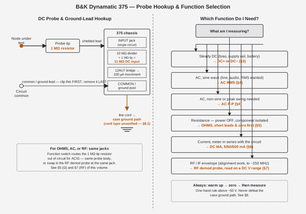
The left half of the figure is the hookup every DC measurement in §3 assumes: ground/common lead clipped first, probe tip second, and — if the cord is the grounded kind — the case tied to earth through the line cord regardless of what the probe is doing (§8.1). The right half collapses §3 through §7 into a one-glance lookup — use it as a bench cheat sheet until the sequence is automatic; Vol 6 folds a version of this same logic into the full instrument cheatsheet alongside the Simpson 311-2’s equivalent procedure.
4.12 Full Range & Function Quick-Reference
One consolidated table, pulled from the 1961 advertisement’s spec block [CONFIRMED], for the moment you just need the numbers without re-reading the procedure above.
Table 7 — Full Range & Function Quick-Reference
| Function | SELECTOR position | Full-scale ranges | Input path |
|---|---|---|---|
| DC volts, positive | DC+ | 1.5, 5, 15, 50, 150, 500, 1500 V | Probe INPUT jack, 11 MΩ (1 MΩ tip + 10 MΩ internal) |
| DC volts, negative | DC− | 1.5, 5, 15, 50, 150, 500, 1500 V | Probe INPUT jack, 11 MΩ (1 MΩ tip + 10 MΩ internal) |
| AC volts, RMS (sine-calibrated) | AC RMS | 1.5, 5, 15, 50, 150, 500, 1500 V | Probe INPUT jack, tip resistor switched out; AC Z [NOT FOUND] |
| AC volts, peak-to-peak | AC P-P | 1.5, 5, 15, 50, 150, 500, 1500 V | Probe INPUT jack, tip resistor switched out; AC Z [NOT FOUND] |
| Resistance | OHMS | 500 Ω, 5 kΩ, 50 kΩ, 500 kΩ, 5 MΩ, 50 MΩ, 1000 MΩ | Probe INPUT jack + COMMON, internal 1.5 V cell, tip resistor switched out |
| DC current | DC MA | 5 mA, 50 mA, 500 mA | DC CURRENT jacks (series path — not the probe) |
| RF / IF envelope | DC+ or DC− (with RF probe fitted) | Reads on whichever DC range fits the demodulated envelope | RF demodulator probe (accessory), to ~250 MHz [LIKELY] |
Table 8 — Full Range & Function Quick-Reference
| Movement | Value |
|---|---|
| Sensitivity | 100 µA full scale [CONFIRMED] |
| Multiplier-resistor tolerance | ±1 % [CONFIRMED] |
| DC input resistance | 11 MΩ, all DC ranges [CONFIRMED] |
| Overall accuracy (DC/AC) | [UNCERTAIN] — obscured in the only located copy of the ad; typical era figures run ~±3 % FS DC / ±5 % FS AC, not confirmed 375-specific |
4.13 End-to-End Field Checklist
The whole volume, compressed into the sequence to actually follow at the bench:
- SELECTOR to OFF. Inspect the cord. If it has a ground pin, plug into a grounded outlet — never a cheater adapter (cord type isn’t verified for this model; treat any ground pin present as load-bearing — §8.1).
- Power up onto any DC or AC position; confirm the drum window illuminates.
- Warm up — let it sit idle, unloaded, for several minutes (§1). Don’t skip this for a precision reading.
- Check mechanical zero with the instrument unpowered or at rest, using the meter’s mechanical zero screw if needed (§2.1).
- Electrical ZERO ADJUST: SELECTOR to DC, short probe tip to COMMON, null the meter with the ZERO control (§2.2).
- Decide what you’re measuring — steady DC, sine AC, non-sine AC, resistance, current, or an RF/IF envelope — and pick the matching SELECTOR position (Figure 4.1, §10).
- For DC: pick DC+ or DC− by the node’s expected polarity; start on the highest range and work down (§3).
- For AC: pick RMS for a known sine, P-P for anything else or for peak-swing work; start high and work down (§4).
- For OHMS: power the circuit under test OFF and isolate the component if practical; short the leads and null with the OHMS control before trusting any reading — this is also your battery check (§5).
- For DC current: power down, break the series path, connect the DC CURRENT jacks, start on 500 mA, re-energize, read, power down again before disconnecting (§6).
- For RF/IF: swap in the RF demodulator probe, SELECTOR to DC, keep the ground lead short, read as a relative (peak/trough) indicator (§7).
- Re-zero periodically on a long session, and always re-zero after any probe or lead change (§2.3).
- Cross-check an unexpected or suspicious reading against the Simpson 311-2 before trusting it (§8.6, Vol 6) — don’t average away a disagreement, diagnose it.
- Shut down: SELECTOR to OFF, disconnect probes from the circuit before disconnecting from the meter, and if you’re about to store the instrument for more than a session or two, pull the ohms battery (§8.5).
Sources
- radiomuseum.org — B&K Dynamatic 375 (tubes, selenium B+, price, size, schematic + photo set): https://www.radiomuseum.org/r/dynascan_k_dynamatic_375.html
- radiomuseum.org — 1961 advertisement spec block (ranges, 11 MΩ input, 100 µA movement, 1½ V battery, ±1% multipliers, size/price): https://www.radiomuseum.org/images/radio/b_k_dynascan_corp/b_k_dynamatic_375_2105857.jpg
- radiomuseum.org — schematic image (title block “B&K MFG CO MODEL 375 VTVM,” drawing no. PM-285M-F): https://www.radiomuseum.org/images/schematic-medium/b_k_dynascan_corp/b_k_dynamatic_375_2095388.png
- BAMA manual archive — B&K 375 (
bk375.djvu, includes AE-1A & PR-38 probe pages + the 1961 ad): http://bama.edebris.com/manuals/b&k/375 - elektrotanya — “B-K DYNAMATIC-375 TUBE VOLTMETER” service manual, 24 pp: https://elektrotanya.com/b-k_dynamatic-375_tube_voltmeter.pdf/download.html
- elektrotanya — “BK PRECISION DYNAMATIC 375 VTVM INCLUDING THE AE-1A AND PR-38 RF PROBES”: https://elektrotanya.com/bk_precision_dynamatic_375_vtvm_including_the_ae-1a_and_pr-38_rf_probes.djvu/download.html
- Antique Radio Forums — “B&K Dynamatic 375 VTVM woes” (grounding fix, divider/bridge component values, battery wiring, 12AU7 + 6AL5 confirmation): https://antiqueradios.com/forums/viewtopic.php?p=1517272, https://antiqueradios.com/forums/viewtopic.php?p=1517468, https://www.antiqueradios.com/forums/viewtopic.php?t=3786
- Surplus Sales of Nebraska — B&K RF Demodulator Probe (AV-1A, “to 250 MHz, for most VTVMs”): https://www.surplussales.com/items/99536/bk-rf-demodulator-probe/
- byan-roper.org (Steve Byan) — switchable VTVM probes (1 MΩ isolation-resistor design; B&K PR-43 for the 177, PR-21/100 kΩ for the 277 FET Multimeter): https://www.byan-roper.org/steve/steve-at-play/antique-electronics-and-2/switchable-vtvm-probes.html
- radiomuseum.org — B&K 177 VTVM (~1970, 12AU7 + 6AL5, battery-less ohms — cited for the AC/ohms-source contrast in §5): https://www.radiomuseum.org/r/dynascan_precision_model_vtvm_177.html