B&K Dynamic 375 VTVM · Volume 5
B&K Dynamatic 375 — Vol 5: Calibration & Refurbishing
A sixty-year-old bridge amplifier will lie to you politely — this is how you catch it, and how you stop a fixable unit from being scrapped for the wrong reason.
5.1 Scope of This Volume
Vol 3 covered what’s inside the case; Vol 4 covered how to drive it on the bench. This volume is about what happens when a 1961 instrument has been sitting — in an attic, in a dead estate’s junk box, on an eBay seller’s shelf — for anywhere from ten to sixty years, and what a careful owner does before, during, and after bringing it back into calibration.
The organizing idea of this volume is a triage order, and it is not the order most people reach for. The instinct on a “dead” tube instrument is to pull the tubes and go hunting for a scope or a tube tester. On the 375, that instinct is wrong often enough to be worth stating as a rule up front:
Note — the best-documented failure mode of this specific instrument is not a tube at all. It’s a loose or oxidized ground connection at the ZERO and OHMS pot bodies, and it presents exactly like a dead or erratic bridge — the symptom a tube-swapper would chase first. §5.2 below walks through it because a real forum thread (“375 woes”) walks through exactly this misdiagnosis and its fix, and it’s the single highest-value thing in this volume.
The rest of the volume follows the instrument outward from that gotcha: the precision divider string that sets DC accuracy (§5.3), the ohms battery and its holder (§5.4), the tubes themselves — cheap, but not the first suspect (§5.5), the drum/indexing mechanism that must be protected rather than serviced (§5.6), a full recalibration walkthrough (§5.7), a symptom-cause-fix reference table (§5.8), and parts sourcing (§5.9).
⚠ Danger — this instrument runs from 117 V, 50–60 Hz line power through an internal power transformer and a selenium B+ rectifier, and it operates a hot 12AU7/6AL5 tube pair inside a metal case with the cover off during service. Read the hub-wide
_shared/legal_ethics.mdbefore opening the case, and see Vol 4 §1 for this instrument’s specific mains and HV precautions. Selenium rectifiers can off-gas an acrid smell if driven into failure — do not power up a just-acquired unit with the cover off and the room unventilated on the first try; see §5.4 and §5.9 for how this interacts with cell-replacement work near the rectifier.
5.2 Baseline: What “Normal” Looks Like Before You Diagnose Anything
A recalibration or repair session is only as good as your baseline. Before touching a screwdriver, establish what the unit does as found and write it down — this is the single most-skipped step in amateur restoration, and it is why “I fixed it” reports from forums are so often unfalsifiable.
5.2.1 Warm-up and thermal settling
Like every tube VTVM, the 375’s 12AU7 bridge amplifier needs to reach thermal equilibrium before its zero point is meaningful. Cathode temperature, tube gas content, and the values of the bridge’s associated resistors all drift slightly during the first several minutes after power-up, and the ZERO control will need to chase that drift.
Note — the exact warm-up time B&K specified for the 375 could not be verified from the sources available for this dive (marked [NOT FOUND] in the facts baseline). Treat 15–20 minutes as a reasonable, conservative floor before trusting a zero or a calibration check — consistent with general tube-VTVM practice and with the instrument’s own general reputation for holding calibration well once settled (see below). If you own a Simpson 311-2 as well, compare warm-up behavior between the two; that comparison is itself a useful diagnostic (Vol 6 §2).
5.2.2 Rezero as a routine, not a symptom
Expect to touch ZERO (with the input shorted or the probe tip lifted, depending on function) at the start of every session, and to touch OHMS (the ohms full-scale adjust, with the ohms probe tips shorted together) every time you switch into the OHMS function after a warm-up. This is normal tube-VTVM behavior, not a fault — a 12AU7 bridge that never needed re-zeroing across a session would be the surprise, not the other way round.
What is worth logging as a possible early symptom:
Table 1 — What is worth logging as a possible early symptom
| Observation | Read as |
|---|---|
| ZERO holds steady session to session, small trim only | Normal aging — routine |
| ZERO wanders noticeably during a session after warm-up | Tube gas/emission drifting, or a marginal bridge resistor — watch it, don’t panic |
| ZERO won’t reach true zero (pot runs out of travel) | Bridge badly unbalanced — check the pot itself, then §5.2, then tube swap |
| Meter reads erratically, jumps, or is simply dead | Check pot grounding before anything else — §5.2 |
| Ohms won’t peak to full-scale no matter how far OHMS is turned | Battery/holder (§5.4) or an ohms-string resistor, not the bridge |
Note — B&K 375s have a reputation among collectors for holding calibration well relative to some contemporaries — this is a secondhand, forum-sourced impression rather than a hard spec, but it matches the instrument’s overall build quality (±1% precision multiplier resistors from the factory, per Vol 2 §2) and is worth mentioning as a reason a “dead” unit is very often a fixable connection problem rather than a genuinely degraded bridge.
5.3 Acquisition Triage — the First Thirty Minutes With a Newly Acquired Unit
Everything above assumes the unit is already on the bench and known-safe to power up. A 375 arriving from an estate sale, a swap meet, or an online auction deserves a short, disciplined triage pass before it’s plugged into mains at all — the same instinct that says “check grounding before blaming tubes” applies one level earlier: check the obvious physical and electrical hazards before you check anything about calibration.
- Visual inspection with the case still closed. Look for a cracked or discolored case, a line cord with brittle or cracked insulation (common on a cord this old — replace pre-emptively rather than trusting it), and confirm the fuse (if externally accessible) is the correct rating rather than a bodge (foil-wrapped fuse, wrong-value substitute, or a solid wire jammed in the holder — all of which show up more often than you’d like on unknown-history gear).
- Open the case before the first power-up, not after. This is the one deviation from “don’t fix what isn’t broken yet” this volume argues for: on a first power-up of an unknown-history unit, you want eyes on the selenium rectifier, the electrolytic capacitors, and the general wiring condition before line voltage ever reaches them, because a shorted selenium rectifier or a leaky electrolytic can fail spectacularly (smoke, off-gassing, occasionally an audible pop) on first power-up after a long dormant period, and you’d rather see that coming than smell it.
- Look specifically for the ohms battery (§5.4) and note its condition before doing anything else — corrosion here is common enough on unknown-history units that it’s worth checking before the case even goes back together for a first power test.
- Check the ZERO/OHMS pot shaft nuts by hand (§5.2) — snug or loose, without disassembling yet. A loose nut found here is diagnostic information worth having before you ever apply power and try to interpret a “dead” reading.
- First power-up: variac-ramped if one is available, watching and listening for smoke, arcing, or unusual smells, with a hand near the switch. This is standard vintage-tube-gear practice (documented in the hub’s variac subproject and safety doc) rather than something specific to the 375, but it applies directly here given the selenium rectifier and the instrument’s unknown power history.
- Only after a clean power-up does the rest of this volume’s diagnostic order apply: warm up, check zero behavior, and work through §5.2 onward as needed.
Note — a unit that fails this triage pass loudly (smoke, a blown fuse immediately on power-up, visible arcing) is not necessarily a lost cause — it just means the PSU-level fault has to be found and cleared before any of the calibration work in this volume is meaningful. General mains-instrument PSU troubleshooting (transformer, rectifier, filter caps) is outside this volume’s verified source material for 375-specific detail; treat it as a prerequisite gate, not a step in the calibration sequence itself.
5.4 The Grounding Gotcha — “375 Woes”: Diagnose This Before You Touch a Tube
This is the section to read in full before doing anything else to a newly acquired 375.
5.4.1 The mechanism
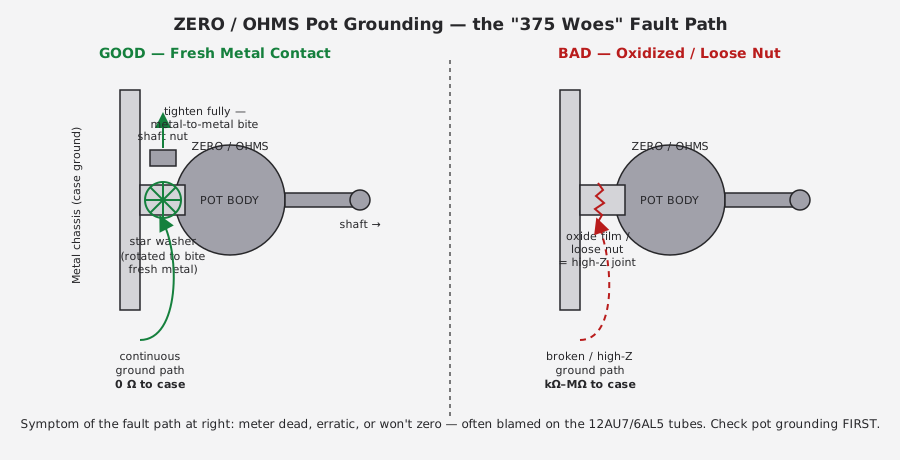
The ZERO and OHMS front-panel controls are potentiometers whose metal bodies, not just their electrical terminals, are part of the circuit’s ground reference. Like most panel-mount pots of the era, each one grounds to the chassis through its own mechanical mounting: the threaded bushing passes through a hole in the front panel, and a shaft nut, torqued down over a lock washer (and ideally a star washer that bites through any paint or oxide to bare metal), is what actually completes that ground path. There is often no separate ground wire from the pot body at all — the mechanical joint is the electrical connection.
That’s a fine design when the nut is freshly torqued onto clean metal. It is a bad design to leave alone for sixty years, because two slow, boring processes work against it constantly:
- The nut backs off. Thermal cycling, handling, shipping vibration, and simple age loosen a nut that was torqued once in 1961 and never touched again.
- The contact oxidizes. Steel, plated brass, and aluminum panel stock all form a thin oxide or corrosion film over decades, and that film is a poor conductor — enough to turn a solid 0 Ω ground into a joint measuring anywhere from a few ohms to megohms, silently, with no visible sign from outside the case.
Either failure — a loose nut or an oxidized joint — puts an unpredictable, non-zero impedance between the pot body and true chassis ground. Because the ZERO and OHMS pots sit directly in the bridge’s balance and reference path, that stray impedance shows up as exactly the symptom you’d expect from a failed or badly drifted 12AU7: a meter that won’t zero, that reads erratically, that jumps around, or that appears simply dead.
⚠ Danger — this is exactly the failure documented in the Antique Radio Forums “B&K Dynamatic 375 VTVM woes” thread, which is the primary source for this section. The thread’s arc is the cautionary tale worth internalizing: a bench that reads dead or erratic gets blamed on the tubes, tubes get swapped, the fault persists, and only then does someone check the pot grounding and find the real cause. Save yourself the tube-swapping round trip — check this first.
5.4.2 The fix
- Power down and unplug the unit; discharge/verify no residual HV per the safety doc before
opening the case (see
_shared/legal_ethics.mdand Vol 4 §1). - Remove the case shell to expose the rear of the front panel and the ZERO/OHMS pot mounting hardware.
- Remove each pot’s shaft nut and its washer stack. Note the orientation before disassembly if the stack looks unusual — most will be a simple lock washer, sometimes with a star (toothed) washer beneath it.
- Clean both mating surfaces to bare metal: the panel-side face around the bushing hole, and the underside of the nut and washer. A fiberglass scratch pen, fine (400–600 grit) abrasive, or a brass brush all work; avoid gouging the panel finish more than necessary since this is a front-panel surface on an instrument whose panel graphics (the DYNAMATIC silk-screen, range legends) are themselves irreplaceable.
- Reinstall with the star washer rotated slightly off its old seating position so its teeth bite into fresh, unmarked metal rather than re-seating in the same worn groove — the specific, documented fix from the source thread.
- Tighten the shaft nut fully. Not gorilla-tight against a plastic bushing, but firm — this joint needs to be a solid mechanical/electrical bond, not a finger-tight placeholder.
- Repeat for the second pot. Do both even if only one function (DC zero vs. ohms) is misbehaving — if one has drifted, the other has seen the same decades of neglect.
- Do this on every newly acquired 375 as a matter of course, whether or not it currently shows a symptom. The source thread frames this explicitly as preventive maintenance for “any newly acquired unit” — the joint degrades invisibly, so “it’s reading fine right now” is not evidence the joint is healthy, only that it hasn’t failed yet.
Note — while the case is open for this fix, this is the natural moment to also inspect the RANGE and FUNCTION SELECTOR switch wafers for the same class of problem — oxidized wiper contacts on a rotary switch produce comparable symptoms (dead or erratic on specific ranges/functions rather than globally) and are worth a visual and continuity check while you’re already inside the case. Switch-wafer service specifics were not part of the verified source material for this dive and are not detailed further here; treat it as a natural extension of the same “check mechanical-electrical joints before blaming active devices” discipline.
5.5 Precision Divider Resistor Drift
Once the ground path is confirmed solid, the next place a 375’s DC accuracy erodes is the precision resistor string that both sets the ±1%-rated attenuation on each range and forms the top half of the bridge’s 11 MΩ DC input divider.
5.5.1 What’s in the string
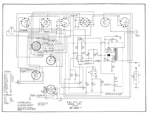
Per the schematic and the forum service thread (Vol 2 §3 covers the full bridge topology; this is the refurb-relevant summary):
Table 2 — refurb-relevant summary)
| Designator | Nominal value | Role |
|---|---|---|
| R21 | 6.8 MΩ | 12AU7 pin 2 grid to ground — top of the DC input divider |
| R25 | 3.3 MΩ | From pin 7 — completes the divider (R21 + R25 ≈ 10 MΩ) |
| R27 | 11 kΩ | Bridge calibration/balance pot |
| R30 | 15 kΩ | Bridge calibration/balance pot |
| R32 | 11 kΩ | Bridge calibration/balance pot |
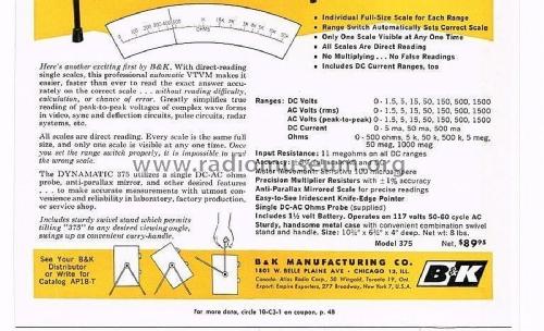
R21 and R25 in series give roughly 10 MΩ at the 12AU7 grid; combined with the 1 MΩ series resistor inside the DC probe tip, that’s the instrument’s specified 11 MΩ DC input resistance on all DC ranges (Vol 2 §4, Vol 4 §2). The range-switched attenuator network ahead of the bridge (not individually itemized in the verified source material) is the factory ±1% precision string the 1961 advertisement calls out explicitly.
5.5.2 Why these parts drift, and which direction
Carbon-composition resistors — the dominant precision-resistor technology in 1961 — are well known to drift upward in value with age, driven by slow oxidation and moisture ingress into the carbon-clay matrix over decades. This is universal VTVM/tube-instrument service knowledge, not a 375-specific finding, but it applies with particular force here because R21 and R25 are megohm-range parts: a small percentage drift on a 6.8 MΩ or 3.3 MΩ resistor is a much larger absolute value than the same percentage drift on a 10 kΩ part, and because these two resistors set the DC input divider ratio directly, their drift shows up as a proportional error across every DC voltage range simultaneously — not a fault isolated to one range.
Note — the calibration pots (R27, R30, R32) are a different risk: as wirewound or carbon-track trimmers, their failure mode is more often mechanical (wiper wear, intermittent contact) than a smooth value drift, and they’re serviceable by cleaning/exercising before being condemned outright — the same “check the connection before you blame the part” discipline as §5.2.
5.5.3 Measurement and replacement procedure
- Isolate the resistor from the circuit before measuring — an in-circuit megohm reading through a live bridge network will be contaminated by parallel paths through the rest of the divider and the tube socket. Lift one leg.
- Measure with a high-input-impedance DMM rated for confident megohm-range readings (most modern bench and handheld DMMs are fine into the tens of megohms; verify your meter’s own accuracy at this range against a known reference if precision matters).
- Compare against nominal with headroom for the era’s tolerance, not against the ±1% precision spec — the original factory tolerance on these was tight, but “still within ±1%, sixty-five years later” is an unreasonable bar. What matters is whether the measured value still supports the calibration you’re trying to hold, and whether it’s drifted enough to explain an observed accuracy problem.
- Replace with modern ±1% metal-film resistors at the same nominal values (6.8 MΩ, 3.3 MΩ, and the associated string values as needed). Metal film doesn’t share carbon-comp’s upward-drift failure mode and is the standard modern substitute in this kind of restoration.
- Recalibrate after any resistor swap — see §5.7. A resistor swap changes the divider ratio even if only slightly, and the whole point of doing this work is to end up more accurate, not just differently inaccurate.
⚠ Danger — R21 sits directly at the 12AU7 control grid inside a circuit whose input can see up to 1500 V full-scale on the top DC range. Confirm the instrument is unplugged and any charge on input-path capacitors has bled down before lifting leads in this area, and treat the whole input attenuator string with the same respect you’d give a working HV probe network.
5.6 Internal Battery-Holder Corrosion
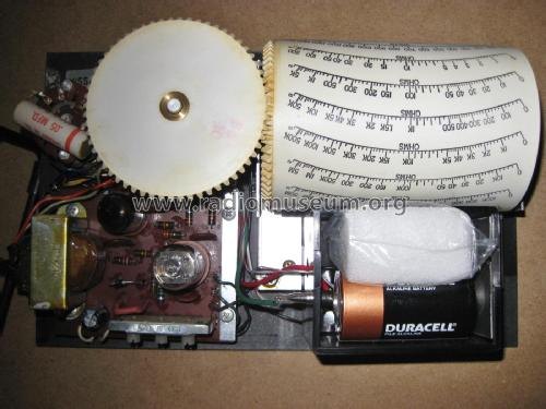
The OHMS function runs from a single internal 1.5 V D-size cell rather than a rectified-AC ohms supply (that battery-less approach came later, on the 177 — see Vol 1’s family sidebar). The cell’s positive terminal feeds the “E” deck of the function switch, and its negative terminal returns to circuit ground; the front-panel OHMS control zeros the scale by adjusting full-scale deflection against whatever the cell is currently delivering.
5.6.1 The failure mode
A single alkaline (or worse, zinc-carbon) D cell left installed for years — the default state of any instrument that sat unused — is a textbook leak risk. Alkaline cells leak potassium hydroxide as their seals age and internal pressure builds from slow self-discharge; the leak product is corrosive to the spring contacts and the sheet-metal holder it sits in. Left long enough, this eats through contact plating, seizes the cell in place, and can spread corrosion to nearby chassis structure.
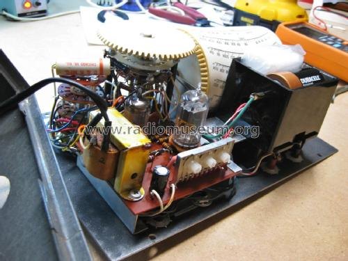
This is universal battery-powered-instrument advice, not 375-specific, but it applies here with the same weight as anywhere: the ohms battery in a 375 that’s been sitting for years is a “when,” not an “if,” corrosion risk, and it’s visible in-photo (a period Duracell D-cell is clearly seen in the chassis internals) making it an easy, cheap thing to inspect early in any service session.
5.6.2 The fix and the storage discipline
- Remove the cell as one of the first steps of any service session on a newly acquired or long-stored unit — don’t wait for an ohms-function symptom to prompt you.
- Inspect the holder and contacts for white/green crust (alkaline leak) or blue-green crust (leak reacting with copper-alloy contacts). Clean with an appropriate contact cleaner or a baking-soda-and-water solution for alkaline residue (standard alkaline-leak neutralization practice), then dry thoroughly.
- Replace corroded spring contacts if the plating is eaten through to base metal — a bare-metal contact will itself corrode faster and give an unreliable, resistance-adding connection even after cleanup.
- Install a fresh 1.5 V D cell only when you’re about to use the OHMS function, and:
- Store the instrument with the cell removed. This is the single most effective preventive measure — a battery that isn’t installed can’t leak into the holder. Keep a spare cell nearby in the case or accessory kit rather than leaving one seated for the long term.
Note — because the cell sits electrically close to (though functionally separate from) the selenium B+ rectifier and the tube socket area on this chassis, a full leak event is worth treating as a “stop and clean before power-up” situation rather than something to power through — see the hub safety doc for handling notes on aged selenium rectifiers, which have their own hazardous-material considerations independent of the battery issue.
5.7 Tube Service — Cheap Parts, but Not the First Suspect
The 375’s entire active measuring path is two tubes: one 12AU7 dual triode running the balanced bridge DC amplifier, and one 6AL5 dual diode running AC rectification for both the RMS and peak-to-peak AC functions (Vol 2 §§2–3). Both are common, inexpensive, still-in-production-or-widely- stocked tube types with no 375-specific selection requirements documented in the sources for this dive.
5.7.1 When a tube swap is the right move
- AC function misbehaves but DC and ohms are fine — points at the 6AL5, since it’s isolated to the AC rectification path.
- DC balance drifts unusually, or won’t null even after §5.2’s grounding fix is confirmed solid — points at the 12AU7, since it’s the bridge amplifier itself.
- General “soft” or noisy readings across functions after grounding and battery are both ruled out — either tube is a reasonable next step; swap the 12AU7 first since it’s in the signal path for every function, DC and AC alike (AC ultimately reads out through the same DC bridge/meter).
5.7.2 The order-of-operations rule
⚠ Danger — and the whole point of this volume: the documented “375 woes” case that anchors §5.2 is, at its core, a story about someone (reasonably) suspecting the tubes first and being wrong. The discipline this volume asks for is: §5.2 grounding check → §5.4 battery/holder → §5.3 divider resistors in scope → only then tube swap. Tubes are cheap and it’s tempting to just throw a fresh pair at a misbehaving unit as a first move, but doing so without ruling out the ground fault means you can “fix” a unit by luck (a tube swap disturbs the socket, incidentally improving a marginal ground elsewhere) without ever understanding what was actually wrong — and you’ll be back chasing the same symptom next time something else shifts slightly.
5.7.3 Socket contact cleaning — the same discipline as §5.2, one more time
Before condemning either tube, pull it and clean its socket contacts — tube sockets of this era use spring-finger contacts that suffer the identical oxidation problem as the ZERO/OHMS pot grounding joints in §5.2, just on a smaller scale and with lower consequence if missed (a socket contact problem tends to show up as intermittent or noisy rather than fully dead, since most tube sockets have several redundant fingers per pin). A contact cleaner formulated for tube sockets (not a general-purpose electrical cleaner that could leave a residue film) and several insertion/removal cycles to wipe the pins is often enough to resolve a marginal reading that would otherwise get blamed on the tube itself. This is worth doing before sourcing a replacement tube, not after — it’s free, it’s fast, and it rules out the same “connection, not component” failure class that dominates this whole volume.
5.7.4 Practical notes
- Both tube types are common enough that NOS and current-production stock are both realistic sourcing paths (§5.9).
- A tube tester (Vol 3’s cross-reference to the hub’s tube-tester subprojects — e.g. the Heathkit TT-1 or Supreme 385 elsewhere in this TestEquipment hub) is useful for screening a swapped-out tube for gross emission failure, but a 12AU7 balance problem in this bridge role can be subtler than a simple emission tester will catch, since the bridge cares about the matching between the two triode sections, not just each section’s raw gain in isolation. Swap-and-compare against a known-good pair is the more reliable field diagnostic.
- After any tube swap, re-zero and recalibrate (§5.7) — a fresh tube’s operating point is never identical to the one it replaced.
5.8 Protecting the Drum/Indexing Mechanism
The DYNAMATIC rotating drum scale is this instrument’s headline feature (Vol 1, Vol 3) and, from a refurb standpoint, its most irreplaceable one.
5.8.1 Why this part gets special handling
Every other component discussed in this volume — resistors, a battery, tubes, even the pots themselves — is a generic part with a modern equivalent or a healthy NOS supply. The drum and its indexing linkage are not. They’re a custom-molded, custom-printed mechanical assembly unique to this instrument family, geared to the RANGE switch so that turning the range knob physically rotates the correct pre-printed scale into the lighted viewing window (Vol 3’s detailed mechanism description). Forum commentary on this class of B&K instrument describes these drum/indexing assemblies as unique to the instrument, making replacement difficult if the mechanism is damaged — there is no drop-in substitute, no compatible donor part from a more common instrument, and no practical way to reproduce the printed scale faces to factory standard.
5.8.2 Handling discipline while the case is open
- Never force the RANGE switch if the drum feels like it’s binding — a stiff rotation is more likely a dry or slightly misaligned gear/indexing point than something requiring force to clear.
- Support the drum assembly, don’t lever against it, when working nearby on the pots, resistor string, or tube sockets — it’s easy to brace a hand or a tool against the nearest available structure inside a cramped chassis, and the drum’s plastic gearing is not the structure to use for that.
- Keep any cleaning or lubrication conservative and localized — a drop of light instrument oil on a documented pivot point is a reasonable maintenance step by analogy to other precision mechanical meter movements in this hub (see the general jeweled-pivot handling notes cross-referenced from Vol 3), but flooding the mechanism, or using a solvent near the printed scale faces, risks damage with no path to repair.
- Photograph the mechanism before any work that requires touching it, specifically so a disassembly can be reversed correctly — there is no factory service literature confirmed available for this specific linkage in the sources gathered for this dive (the BAMA and elektrotanya manual packages remain access-gated as of this writing — see Sources, below), so your own documentation may be the only reference you have if something needs to come back together weeks later.
Note — this is the one part of the instrument where the right refurb answer is often “leave it alone.” If the drum indexes correctly and the scale is legible, the highest-value thing you can do for it is nothing beyond routine dust control — resist the urge to “improve” a mechanism you can’t source parts for.
5.9 Recalibration Walkthrough
This section assumes the grounding fix (§5.2) has already been done or confirmed, the battery/holder have been inspected (§5.4), and any resistor or tube replacements from §§5.3/5.5 are complete. It’s the sequence to run any time the instrument has been serviced, and periodically thereafter as routine bench discipline.
5.9.1 Step by step
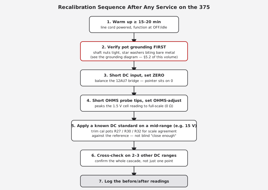
- Warm up the instrument for at least 15–20 minutes with the line cord powered (§5.1’s baseline discussion covers why this floor is conservative-but-reasonable given the unverified factory spec).
- Verify pot grounding is solid — even if you fixed it earlier this session, this is cheap insurance before trusting any reading that follows. Wiggle-test the shaft nuts by hand; they should not turn.
- Set ZERO. With the DC input shorted (or per the specific procedure for the function/polarity in use — see Vol 4’s operating sequence), adjust ZERO until the pointer sits precisely on the scale’s zero mark.
- Set OHMS full-scale. Short the ohms probe tips together and adjust the OHMS control until the pointer reads full-scale (0 Ω) on the ohms scale. If it won’t reach full-scale no matter how far you turn the control, suspect the battery/holder (§5.4) before the pot itself.
- Apply a known DC voltage standard on a convenient mid-range — 15 V is a practical choice, well inside the 1.5–1500 V cascade and easy to source a reference for (a calibrated bench DMM or a dedicated voltage reference/calibrator elsewhere in this TestEquipment hub both work). Compare the 375’s indicated reading against the reference.
- Trim the calibration pots (R27, R30, R32 — §5.3) if the discrepancy exceeds what you’re willing to accept, working toward agreement with the reference rather than toward an arbitrary “it looks about right” pointer position.
- Cross-check on at least two or three other DC ranges across the cascade (e.g. 5 V, 50 V, 500 V) rather than trusting a single-point trim. Because R21/R25 set the input divider that every DC range shares, a single-point trim can mask a proportional error that only becomes visible when you check a second range.
- Log before/after readings — reference voltage, indicated voltage, and range, for each check point — in this instrument’s service record. Engineer’s-logbook discipline: “15.00 V reference read as 15.4 V indicated before trim, 15.05 V after — R30 trimmed 3° CW,” not “adjusted until it looked right.”
Note — AC accuracy calibration (against a known AC RMS or peak-to-peak reference) follows the same discipline but through the 6AL5 rectifier path rather than the DC bridge directly; the source material for this dive did not surface 375-specific AC trim points beyond the shared bridge/meter readout, so treat AC calibration as inheriting whatever DC calibration accuracy you’ve already established, verified independently against an AC reference where one is available.
5.10 Failure-Mode Reference Table
A consolidated symptom-first reference for the whole volume — read top to bottom in roughly the diagnostic priority this volume argues for.
Table 3 — Failure-Mode Reference Table
| Symptom | Likely cause | Fix | Volume ref |
|---|---|---|---|
| Meter dead or erratic, all functions | Loose/oxidized ZERO or OHMS pot ground (shaft nut/star washer) | Clean joint to bare metal, reseat star washer off its old position, retighten nut | §5.2 |
| Won’t hold zero, or ZERO pot runs out of travel | Bridge badly unbalanced — grounding fault, or genuine 12AU7 drift | Rule out §5.2 first; if solid, suspect the 12AU7 | §5.2, §5.5 |
| Ohms won’t reach full-scale on OHMS-adjust | Weak/dead 1.5 V cell, or corroded battery holder contacts | Replace cell; clean/replace holder contacts if corroded | §5.4 |
| Ohms reads erratically or intermittently | Corroded battery contact (intermittent), or OHMS pot grounding | Clean battery contacts; check §5.2 fix | §5.4, §5.2 |
| DC readings off by a consistent proportional amount across all ranges | R21/R25 (megohm divider string) drifted upward | Measure out-of-circuit, replace with 1% film, recalibrate | §5.3, §5.7 |
| DC reading off on one specific range only | Range-switch attenuator resistor for that range, or switch wiper contact | Inspect range-switch wafer contacts; check that range’s series resistor | §5.2 (switch note), §5.3 |
| AC (RMS or P-P) readings off, DC and ohms fine | 6AL5 rectifier drifted or weak | Swap 6AL5, recalibrate AC | §5.5, §5.7 |
| General noisy/soft readings across all functions, grounding/battery/resistors already ruled out | 12AU7 bridge tube marginal | Swap 12AU7 (verify grounding first — see the order-of-operations rule), recalibrate | §5.5, §5.7 |
| Green/white crust near the battery holder or nearby chassis | Alkaline cell leak | Neutralize residue, clean/replace contacts, store with cell removed going forward | §5.4 |
| RANGE knob stiff, drum doesn’t index cleanly to the lighted window | Drum/indexing linkage dry or slightly misaligned — do not force it | Inspect gently, minimal targeted lubrication only, photograph before any disassembly | §5.6 |
| Won’t power on at all | Line cord/fuse/power transformer/selenium rectifier — general PSU fault, not covered in depth here | Standard mains-instrument PSU triage per the hub safety doc; treat selenium rectifier as a hazardous-material item | See _shared/legal_ethics.md |
5.11 Parts and Probe Sourcing
None of the parts this volume calls out as replaceable are exotic. That’s worth stating plainly, because it’s easy to look at a sixty-five-year-old instrument with an irreplaceable printed-scale drum mechanism (§5.6) and assume the whole thing is similarly fragile to source for. It isn’t — the drum is the outlier, not the rule. Tubes, a D-cell battery, precision film resistors, and probe wire are all either generic modern electronics-distributor stock or common enough in the vintage-radio hobby market that sourcing is rarely the bottleneck; time and diagnostic discipline are.
Table 4 — Parts and Probe Sourcing
| Part | Source path | Notes |
|---|---|---|
| 12AU7 tube | Common; current-production (JJ, Electro-Harmonix, etc.) and NOS both widely available through the usual tube-supply retailers and auction sites | No 375-specific selection criteria found in sources for this dive; a matched or tightly specced pair is a reasonable extra step given its balanced-bridge role, though not confirmed as a factory requirement |
| 6AL5 tube | Common; NOS and some current-production availability | Same general sourcing path as the 12AU7 |
| 1.5 V D cell | Any standard alkaline D cell, hardware/grocery store | Install only when using OHMS; remove for storage (§5.4) |
| Precision film resistors (R21 6.8 MΩ, R25 3.3 MΩ, and associated string values) | Standard electronics distributors (Mouser, Digi-Key, etc.) — ±1% metal film in the needed values and voltage ratings | Confirm voltage rating is adequate for the position — these sit in a divider that can see up to 1500 V full-scale |
| DC-AC-Ohms probe (the single probe supplied with the instrument) | Wear item; period B&K probes surface on the secondary market; a generically compatible high-Z probe can be fabricated if the original is missing, matching the 1 MΩ series-resistor-with-bypass-switch design described in Vol 2 §4/Vol 4 | Confirm the 1 MΩ value and the AC/ohms bypass switching behavior against Vol 2 before fabricating a substitute |
| RF demodulator probe (AV-1A class, rated to ~250 MHz “for most VTVMs”) | NOS units still surface through surplus-electronics dealers (e.g. Surplus Sales of Nebraska) | Accessory, not supplied standard — see Vol 4/Vol 2 for what it adds |
| Drum/indexing mechanism | No sourcing path identified. Unique to this instrument family, per forum commentary. | Protect, don’t attempt to replace — §5.6 |
| Front-panel graphics/silk-screen | No sourcing path identified for reproduction | Handle the panel gently during §5.2’s pot service — the DYNAMATIC branding and range legends are irreplaceable in-kind |
Note — if a probe or precision resistor need ever exceeds what a generic electronics distributor stocks, the Simpson 311-2 dive (the sibling instrument on Jeff’s own two-VTVM bench, cross-referenced throughout this dive and in full in Vol 6 §2) documents a parallel but independently-sourced probe and precision-resistor ecosystem — comparing notes between the two instruments’ service threads is often productive, since both are contemporaries solving the same high-Z-input problem with the same era of parts.
5.12 Building a Before/After Service Record
Every section of this volume assumes you’re keeping a written record — the hub-wide writing convention (Vol 4, and the TestEquipment project standard generally) calls for exactly this: specific, numeric, before-and-after, not “adjusted until it looked right.” For a restoration spread across several sessions on an instrument with no complete factory service manual confirmed accessible (see Sources, below), your own log is doing double duty — it’s both the calibration record and, in practice, the closest thing to a service manual for this specific unit’s history that will exist going forward.
A minimal but useful entry format:
2026-XX-XX — B&K Dynamatic 375, S/N [xxxx]
Session: grounding fix + recal
- Found: ZERO pot shaft nut finger-loose; OHMS pot nut snug. Meter dead on DC+ at session start.
- Action: cleaned both pot bushings to bare metal, reseated star washers rotated ~30° off old
  position, retorqued both shaft nuts.
- Result: meter responds normally on all functions after the fix. No tube swap performed.
- Recal: warmed 20 min. ZERO set with input shorted. OHMS set with probe tips shorted.
  15.00 V reference (Fluke 87V) read as 15.05 V indicated on the 15 V DC range — within
  acceptable margin, no R27/R30/R32 trim performed.
  Cross-checked 5 V range: 5.00 V ref read 5.02 V indicated. 50 V range: 50.0 V ref read 50.3 V
  indicated (0.6%) — acceptable, logged for trend-watching next session.
- Battery: 1.5 V D cell present, no visible corrosion, tested 1.52 V OCV — left installed since
  unit is in active use this week; will pull before extended storage.
- Next: none required. Revisit R21/R25 drift only if a future session shows the 50 V-range
  discrepancy has grown.
This kind of entry accomplishes three things a vague “fixed it” note doesn’t: it gives a future session (yours or someone else’s) a documented starting baseline, it turns a soft judgment call (“acceptable margin”) into a number someone else can re-evaluate later, and it creates the trend data that distinguishes ordinary tube-VTVM zero drift from a genuinely worsening fault — exactly the distinction §5.1 draws between routine rezero and an escalating symptom.
Note — if this 375 and the Simpson 311-2 are being cross-checked against each other as a matter of course (Vol 6 §2’s two-VTVM bench discipline), log both instruments’ readings on the same reference point in the same session. A divergence that shows up on one VTVM but not the other is often more diagnostic than either instrument’s absolute reading against a bench DMM alone.
5.13 Cross-References
- Vol 2 — the balanced-bridge, AC rectifier, and ohms circuit theory that explains why R21/R25, the 12AU7, the 6AL5, and the ohms battery each matter to accuracy.
- Vol 3 — the drum/indexing mechanism’s full mechanical description, and the pot/switch layout on the chassis referenced throughout §5.2’s fix.
- Vol 4 — safety precautions for opening the case and working near mains/HV, and the normal operating sequence (warm-up, zero, function selection) this volume’s recalibration walkthrough extends into a service context.
- Vol 6 — the cheatsheet quick-reference and the two-VTVM bench comparison against the Simpson 311-2 VTVM, including how the two instruments’ service histories and drift behavior compare on Jeff’s own bench.
- Simpson 260 Series 8 — the loadable 20 kΩ/V VOM this VTVM’s 11 MΩ input out-classes on high-impedance tube-circuit nodes (grid bias, screen supply, AVC lines) — relevant context for why a 375 in good calibration is worth the refurb effort documented in this volume, rather than defaulting to the VOM already on the bench.
_shared/legal_ethics.md— the hub-wide bench-safety rules (mains, HV, selenium rectifiers, and other era-typical hazardous materials) that govern every service step in this volume.
Sources
- Antique Radio Forums — “B&K Dynamatic 375 VTVM woes” (the grounding/pot-body fix; R21 6.8 MΩ, R25 3.3 MΩ, R27/R32 11 kΩ, R30 15 kΩ; battery wiring to the “E” deck terminal 12; 12AU7 + 6AL5 tube roles): https://antiqueradios.com/forums/viewtopic.php?p=1517272, https://antiqueradios.com/forums/viewtopic.php?p=1517468, and https://www.antiqueradios.com/forums/viewtopic.php?t=3786
- radiomuseum.org — B&K Dynamatic 375 (tubes, selenium B+ rectifier, year, price, size, schematic and photo set): https://www.radiomuseum.org/r/dynascan_k_dynamatic_375.html
- radiomuseum.org — 1961 advertisement spec block (ranges, 11 MΩ input, 100 µA movement, 1½ V battery, ±1% precision multiplier resistors, size/price): https://www.radiomuseum.org/images/radio/b_k_dynascan_corp/b_k_dynamatic_375_2105857.jpg
- radiomuseum.org — schematic image (title block “B&K MFG CO MODEL 375 VTVM,” drawing no. PM-285M-F): https://www.radiomuseum.org/images/schematic-medium/b_k_dynascan_corp/b_k_dynamatic_375_2095388.png
- BAMA manual archive — B&K 375 service manual package (
bk375.djvu, includes AE-1A and PR-38 RF probe documentation and the 1961 advertisement; access-gated as of this dive — see facts baseline §8): http://bama.edebris.com/manuals/b&k/375 - elektrotanya — “B-K DYNAMATIC-375 TUBE VOLTMETER” service manual, 24 pp (access-gated as of this dive): https://elektrotanya.com/b-k_dynamatic-375_tube_voltmeter.pdf/download.html
- elektrotanya — “BK PRECISION DYNAMATIC 375 VTVM INCLUDING THE AE-1A AND PR-38 RF PROBES” (djvu package listing, access-gated): https://elektrotanya.com/bk_precision_dynamatic_375_vtvm_including_the_ae-1a_and_pr-38_rf_probes.djvu/download.html
- Surplus Sales of Nebraska — B&K RF Demodulator Probe (AV-1A class, “to 250 MHz, for most VTVMs”): https://www.surplussales.com/items/99536/bk-rf-demodulator-probe/
- byan-roper.org (Steve Byan) — switchable VTVM probe design notes (1 MΩ isolation-resistor probe architecture, contrasted against the later 277 FET Multimeter’s 100 kΩ PR-21 probe): https://www.byan-roper.org/steve/steve-at-play/antique-electronics-and-2/switchable-vtvm-probes.html
- radiomuseum.org — B&K 177 VTVM (successor model, ~1970, same 12AU7 + 6AL5 tube complement but battery-less ohms supply — referenced for contrast on the ohms-battery servicing this volume covers): https://www.radiomuseum.org/r/dynascan_precision_model_vtvm_177.html