B&K Dynamic 375 VTVM · Volume 6
B&K Dynamatic 375 — Vol 6: Cheatsheet & the Two-VTVM Bench
Everything on one laminate: specs, full range set, quick-steps, refurb order, safety don'ts, and the complete 375-vs-311-2 bench-pair comparison.
6.1 Purpose of This Volume
Vols 1-5 built the case for this instrument, explained the balanced-bridge circuit, walked the hardware and the “Dynamatic” drum scale, and covered operation and refurb in narrative form. This volume compresses all of it into tables you can find in ten seconds with the meter warmed up and a probe in your hand — plus the one comparison every owner of this bench actually wants: 375 or 311-2, and why both.
No photos in this volume — it is meant to print on a couple of laminated cards, not to be pretty. One diagram (§7) summarizes the two-instrument bench signature side by side.
Note — Every number below traces to Vols 1-5 and, behind them, to the primary B&K sources: the 1961 advertisement spec block, the radiomuseum schematic/photo set, and the Antique Radio Forums “375 woes” service thread. Where a figure is marked [UNCERTAIN] or [NOT FOUND], that flag is preserved from the source research — treat it as exactly as solid as the tag says, no more.
6.2 Quick Specs
Table 1 — 1. Quick Specs
| Parameter | Value | Detail |
|---|---|---|
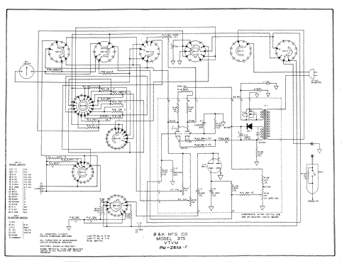
| Type | All-tube VTVM (12AU7 balanced-bridge DC amplifier + 6AL5 AC rectifier). Not FET/solid-state — that’s the later Model 277. | Vol 2 §1-§2 |
| Active devices | 12AU7 (dual triode, balanced-bridge DC amplifier) · 6AL5 (dual diode, AC rectifier, RMS and peak-to-peak) | Vol 2 §1-§2, Vol 3 §4 |
| Power-supply rectifier | Selenium rectifier for B+ — a hazardous-materials item on any pre-1980s unit; see §5 below | Vol 2 §4 |
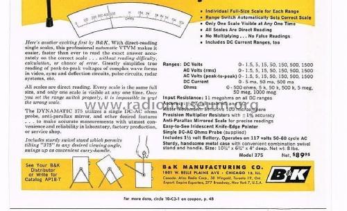
| DC input resistance | 11 MΩ on all DC ranges (1 MΩ probe-tip resistor + 10 MΩ internal divider — the classic VTVM figure) | Vol 2 §1, Vol 3 §3 |
| AC input impedance | [NOT FOUND] as a stated 375 number — do not repeat the 177’s ~11 MΩ AC spec for the 375 | Vol 2 §1 |
| Meter movement | 100 µA full-scale, most likely jeweled-pivot D’Arsonval — “taut-band” is [UNCERTAIN], treat as unverified/probably not | Vol 3 §5 |
| Scale / pointer | Anti-parallax mirrored scale + iridescent knife-edge pointer, on the rotating “Dynamatic” drum — see §1.1 below | Vol 3 §5 |
| Front-panel controls | FUNCTION SELECTOR (OFF / AC P-P / AC RMS / DC+ / DC− / OHMS / DC MA) · RANGE knob · OHMS (ohms-adjust) · ZERO · DC CURRENT jacks | Vol 3 §2 |
| Precision-resistor accuracy | ±1 % multiplier/divider resistors | Vol 4 §3 |
| Overall accuracy (%FS) | [UNCERTAIN] — obscured by a watermark in the only ad image located; typical era figures run ~±3 % DC / ±5 % AC but treat as unconfirmed for this specific model | Vol 4 §3 |
| Ohms battery | 1.5 V D-size alkaline cell, battery-only (used exclusively for the OHMS function) | Vol 3 §4, Vol 5 §6 |
| Power | 117 V AC, 50-60 Hz | Vol 2 §4 |
| Case | Metal, with combination swivel-stand/tilt-bail handle | Vol 3 §1 |
| Size / weight | 10½ × 6½ × 4 in / 267 × 152 × 102 mm · ~8 lb net | Vol 3 §1 |
| dB scale | [NOT FOUND] — the ad’s range block lists none; AC is split into separate RMS and peak-to-peak functions instead | Vol 3 §5 |
| Introduced / era | 1961; BAMA/manual package includes a 1961 ad; production likely ran into the mid-1960s [LIKELY, one 1964-captioned listing] | Vol 1 §1 |
| Original price | $89.95 net (1961 ad); radiomuseum lists $90.00 | Vol 1 §1 |
| Manufacturer | B&K Manufacturing Co., Chicago, IL — later Dynascan Corp., today’s B&K Precision | Vol 1 §1 |
| Lineage | 375 (1961, tube, drum) → 177 (~1970, tube, flat scale) → 277 (~1972+, solid-state FET). The 177/277 are successors, not predecessors. | Vol 1 §1 |
Note — The scaffold errors this dive corrected, in one line each: it’s a genuine tube VTVM, not “solid-state bridging to FET” — that description belongs to the 277. The 177/277 are LATER models, not earlier ones the 375 “bridges from.” If you find an older note anywhere in this project repeating either error, this volume — and Vol 1/Vol 2 — are the corrected source of truth.
6.2.1 The “Dynamatic” drum — the one-line explanation
Instead of one crowded multi-scale meter face, the 375 prints one individual full-size scale for every range around a rotating plastic drum. Turning the RANGE switch mechanically rotates the correct scale into a lighted window — only one direct-reading scale is ever visible, so there is no multiplying and no false readings. This is the “DYNAMATIC” the name badge refers to, and it is the single most distinctive — and most fragile, effectively unobtainable if broken — mechanism in the instrument. Full mechanism detail: Vol 2 §3, Vol 3 §5.
6.3 Full Range Set
6.3.1 DC volts
Table 2 — 2.1 DC volts
| Range (full scale) | Notes |
|---|---|
| 1.5 V | |
| 5 V | |
| 15 V | |
| 50 V | |
| 150 V | |
| 500 V | |
| 1500 V | Direct-reading ceiling — no HV probe is documented for the 375 (see §2.6) |
- 7 ranges. DC+ / DC− on the FUNCTION SELECTOR gives manual polarity reversal, so you can read positive- or negative-going DC without swapping leads. Input resistance is 11 MΩ on every range. Detail: Vol 3 §2, Vol 4 §3.
6.3.2 AC volts — RMS
Table 3 — 2.2 AC volts — RMS
| Range (full scale, RMS) |
|---|
| 1.5 V |
| 5 V |
| 15 V |
| 50 V |
| 150 V |
| 500 V |
| 1500 V |
- 7 ranges, identical cascade to DC volts. Rectified by the internal 6AL5. Detail: Vol 2 §2.
6.3.3 AC volts — peak-to-peak
Table 4 — 2.3 AC volts — peak-to-peak
| Range (full scale, p-p) |
|---|
| 1.5 V |
| 5 V |
| 15 V |
| 50 V |
| 150 V |
| 500 V |
| 1500 V |
Note — Unlike some contemporaries (the sibling Simpson 311-2 uses a separate p-p cascade — 4/14/40/140/400/1400/4000 V p-p), the 375’s peak-to-peak function shares the same numeric range cascade as its RMS and DC functions per the 1961 ad’s spec block. Read the FUNCTION SELECTOR position (AC RMS vs AC P-P), not a different range number, to know which calibration you’re on. Detail: Vol 2 §2, Vol 3 §3.
6.3.4 DC current — the unusual one
Table 5 — 2.4 DC current — the unusual one
| Range (full scale) |
|---|
| 5 mA |
| 50 mA |
| 500 mA |
Note — Most VTVMs are voltage/resistance only. The 375’s inclusion of DC current ranges is a genuine differentiator — the 1961 ad calls it out explicitly (“Includes DC Current Ranges, too”). Jacks are at the panel bottom, separate from the DC-AC-OHMS input jack. This is one of the two rows that make the 375’s “signature” distinct from the Simpson’s — see §7. Detail: Vol 3 §2-§3.
6.3.5 Ohms
Table 6 — 2.5 Ohms
| Range (full scale) |
|---|
| 500 Ω |
| 5 kΩ |
| 50 kΩ |
| 500 kΩ |
| 5 MΩ |
| 50 MΩ |
| 1000 MΩ (1 GΩ) |
- 7 ranges, full-scale values as printed in the 1961 ad (contrast with the Simpson’s center-scale ohms table — see §7). Powered by the internal 1.5 V D-cell. No HV probe is documented for the 375. Detail: Vol 2 §3, Vol 3 §3.
6.3.6 Probes at a glance
Table 7 — 2.6 Probes at a glance
| Probe | Spec | Notes |
|---|---|---|
| DC-AC-Ohms probe (standard, supplied) | Contains the 1 MΩ series isolating resistor for DC; per standard B&K/era design the resistor is switched out (shorted) for AC and Ohms [LIKELY by analogy to sibling B&K probes] | The one probe that ships with the unit — do all three functions (DC/AC/Ohms) through it |
| RF demodulator probe (accessory: AE-1A / PR-38) | AV-1A-class demodulator, rated “to 250 MHz, for most VTVMs” [LIKELY]; whether the exact AE-1A/PR-38 shares that identical spec is [UNCERTAIN] | Documented as included in the manual package title, but is a separate accessory from the base probe |
| HV probe | [NOT FOUND] — no HV probe documented in the sources read for this dive | The 375 reads to 1500 V DC direct and stops there per the confirmed sources |
6.4 Operating Quick-Steps
Follow in order. Skipping the zero steps is the single most common source of a “the meter’s drifted” service call that turns out to be user error — and on this instrument, a “dead meter” call that turns out to be a loose pot nut (§4 step 1) is the second most common.
- Warm up. Power on, let the tube stage reach thermal equilibrium before trusting a reading — like every tube VTVM, the 375’s bridge tube (12AU7) must stabilize before the meter will hold zero. Specific warm-up time for this model is [NOT FOUND]; give it several minutes minimum, longer for calibration-grade work. Detail: Vol 4 §1.
- Mechanical zero. With power off, confirm the pointer sits exactly on its mechanical rest mark in the drum window. This is a physical adjustment (typically a slotted screw under/behind the scale), separate from the electrical ZERO control below — do it once per session, or whenever the unit has been moved or bumped. Detail: Vol 4 §2.
- Set the FUNCTION SELECTOR and RANGE. FUNCTION SELECTOR to AC P-P / AC RMS / DC+ / DC− / OHMS / DC MA as needed; RANGE knob picks the range — this is also what rotates the correct scale into the Dynamatic drum window. Start on a range at or above your expected reading.
- ZERO ADJUST (electrical). With the probe tip shorted to ground (or no input), turn ZERO until the meter reads exactly 0. This balances the 12AU7 bridge and should be rechecked whenever you change range or function, and periodically as the tube ages. Detail: Vol 2 §1, Vol 4 §2.
- Measure. Connect ground first, then probe tip to the test point. On OHMS, the circuit under test must be unpowered — the internal 1.5 V D-cell supplies the test current; any external voltage on the node gives a false reading and risks the meter/bridge.
- OHMS is your ohms-battery test, not just a zero. Short the probe and ground leads on the OHMS function and turn the OHMS (ohms-adjust) control for a full-scale deflection. If it can’t reach full scale, the internal 1.5 V D-cell is dead — replace it before trusting any ohms reading. Run this check at the start of any ohms session, not only when something looks wrong. Detail: Vol 2 §3, Vol 5 §6.
- Re-zero on every range or function change, and periodically as the 12AU7 ages even within one session. It takes two seconds and it is the difference between a real reading and a bridge-imbalance artifact.
Note — DC+ / DC− polarity reversal is a manual FUNCTION SELECTOR position on this instrument — there is no documented zero-center galvanometer mode (the sibling Simpson 311-2 has one; see §7). If you need a center-scale null for balance/discriminator work, that is a 311-2 job, not a 375 job. Detail: Vol 3 §2, §7 below.
6.5 Refurb Quick Steps
Full narrative lives in Vol 5; this is the order-of-operations summary for a bench session — and the order matters, because the documented failure case for this exact instrument was a bad ground, not bad tubes.
- Check the ZERO and OHMS pot grounding FIRST, before you touch anything else. This is the single documented “375 woes” failure mode: the pot bodies ground to the metal case through their mounting, and a loose shaft nut or dirty/oxidized pot-to-case contact makes the meter dead or erratic. Fix: remove, clean, and reinstall the pots with the star washers rotated slightly to bite fresh metal, and tighten the pot shaft nuts immediately on any newly acquired unit — do this before chasing tubes or resistors. Detail: Vol 5 §1-§2.
- Battery next. The single 1.5 V D-cell for ohms is a classic leak/corrosion point. Clean the holder, observe polarity, and leave the cell out during storage to prevent a future leak. Detail: Vol 5 §6.
- Tubes — but only after grounding is confirmed good. 12AU7 and 6AL5 are both cheap, abundant, easy swaps for balance/AC-rectifier problems. The documented “375 woes” case shows a bad ground, not the tubes, was the real fault — verify pot grounding (step 1) before you spend money on tubes chasing a symptom that grounding will fix for free. Detail: Vol 5 §3.
- Check the high-value divider/multiplier resistors for drift. The precision string carries the ±1 % accuracy spec; the usual drift-upward suspects are the megohm-range parts documented from the bridge/divider network — R21 (6.8 MΩ, 12AU7 pin 2 grid to ground) and R25 (3.3 MΩ, from pin 7) — which together with the 1 MΩ probe resistor set the 11 MΩ DC input. Replace with ±1 % film parts and recalibrate if out of tolerance. Detail: Vol 2 §1, Vol 5 §4.
- Recalibration order: balance the bridge with ZERO, set ohms full-scale with OHMS (ohms-adjust), then trim the calibration pots — R27 and R32 (11 kΩ each) and R30 (15 kΩ) — against a known DC standard on the appropriate range. [LIKELY, inferred from the pot map — do the zero/ohms steps first, they are what the cal pots are trimmed against.] Detail: Vol 5 §5.
- Protect the drum. The rotating “Dynamatic” scale/indexing mechanism is unique to this instrument and effectively unobtainable if damaged — handle the RANGE switch gently, don’t force a sticky detent, and don’t disassemble the drum drive unless you have to. This is the one part on the whole instrument you cannot simply order a replacement for. Detail: Vol 2 §3, Vol 5 §7.
- Probe sourcing. The single DC-AC-Ohms probe and the RF demodulator probe are the wear items. B&K/Dynascan RF demod probes in the AV-1A class (250 MHz) still surface as NOS (Surplus Sales of Nebraska carried one at time of writing) — the base DC-AC-Ohms probe is the harder one to replace like-for-like. Detail: Vol 5 §7.
6.6 Safety Don’ts
⚠ Danger — Full bench-discipline rules (mains, HV, hazardous vintage materials) live in the shared
_shared/legal_ethics.md. The points below are the 375-specific subset.
- Don’t skip the pot-grounding check on a newly acquired unit. A “dead” or erratic 375 is more likely a loose ZERO/OHMS pot shaft nut than a bad tube or blown resistor — see §4 step 1. Chasing tubes first wastes money and time on the documented failure mode.
- Don’t measure ohms on a powered circuit. The internal 1.5 V D-cell is the ohms source; any external voltage on the node under test gives a false reading and risks the meter/bridge — same rule as any VTVM.
- Don’t force the RANGE switch or drum mechanism. The Dynamatic drum’s indexing linkage is unique to this instrument and cannot be replaced if broken — a sticky detent is a service item, not something to power through.
- Treat the selenium B+ rectifier as a hazardous-materials item. Selenium rectifiers are a known vintage-gear hazard (they can produce toxic selenium-oxide fumes if they fail catastrophically / overheat) — handle per the shared safety doc, and don’t power up a unit with a visibly bulged or discolored selenium stack without ventilation precautions.
- Don’t trust a reading taken right after a range or function change without re-zeroing. The bridge zero shifts on function/range changes; an un-rezeroed reading is a bridge-imbalance artifact, not a measurement. Detail: §3 step 7.
- Don’t assume this unit has a dB scale or a zero-center galvanometer mode. Neither is documented for the 375 — the Simpson 311-2 has the zero-center mode, the 375 does not; see §7.
- Don’t assume a fixed AC input impedance number for the 375. It is [NOT FOUND] in verified sources — do not repeat the later 177’s ~11 MΩ AC spec as if it were confirmed for this model.
- One-hand rule above ~50 V, per the shared safety doc — applies to any probing inside the case with power applied. B+ inside the chassis is well above that threshold even in this modest VTVM.
6.7 Troubleshooting Quick-Reference
A symptom-to-cause table, ordered so you check the cheap/likely thing before the expensive/unlikely thing — same discipline as §4’s refurb order.
Table 8 — 6. Troubleshooting Quick-Reference
| Symptom | Most likely cause | Check before you replace anything |
|---|---|---|
| Meter dead or erratic, no reading at all | Loose/dirty ZERO or OHMS pot-to-case ground — the documented “375 woes” failure | Remove, clean, and reinstall the pots with star washers rotated to bite fresh metal; tighten shaft nuts. Do this before swapping tubes. Detail: §4 step 1. |
| Can’t zero the meter on DC/AC (ZERO won’t reach 0) | 12AU7 bridge unbalanced — could be a weak/mismatched tube, or a cold unit that hasn’t finished warming up | Confirm full warm-up first; then swap the 12AU7 (cheap, common) |
| Ohms reads low / OHMS control can’t reach full-scale zero | Dead or corroded 1.5 V D-cell | Replace the battery — this is the built-in battery test, see §3 step 6 |
| Ohms readings drift or look consistently high on the megohm ranges | High-value divider resistor drift (R21 6.8 MΩ, R25 3.3 MΩ are the usual upward-drift suspects) | Measure against schematic values; replace with ±1 % film parts if out of tolerance. Detail: §4 step 4. |
| AC readings off but DC is fine | 6AL5 rectifier weak, or the AC-position probe-tip switch not fully shorting the 1 MΩ resistor | Swap the 6AL5 (cheap, common); check probe slide-switch contact |
| Drum scale sticks, doesn’t index cleanly to the RANGE switch position | Mechanical wear/dirt in the drum drive linkage — do not force it | Gentle cleaning/lubrication of the indexing mechanism; this is the one part that can’t be replaced if broken. Detail: §4 step 6. |
| Reading looks plausible but disagrees with the Simpson 311-2 on the same node | One of the two meters needs re-zeroing, or one has an uncalibrated drift issue | Re-zero both, re-check warm-up on both, then re-measure — see §7’s whole-bench discipline |
| Case/chassis smells acrid or a component looks bulged/discolored near the power transformer | Possible failing selenium rectifier | Power down immediately; do not continue to operate — see §5’s hazardous-materials note |
6.8 The Two-VTVM Bench: B&K Dynamatic 375 vs Simpson 311-2
Jeff runs these two side by side on purpose. Two independently-zeroed bridges reading the same node catch a drifting calibration that a single meter can’t flag on its own — if the 375 and the 311-2 agree within their combined tolerance, trust the reading; if they don’t, one of them needs attention before either result is trustworthy. Full sibling dive: Simpson Model 311-2 VTVM.
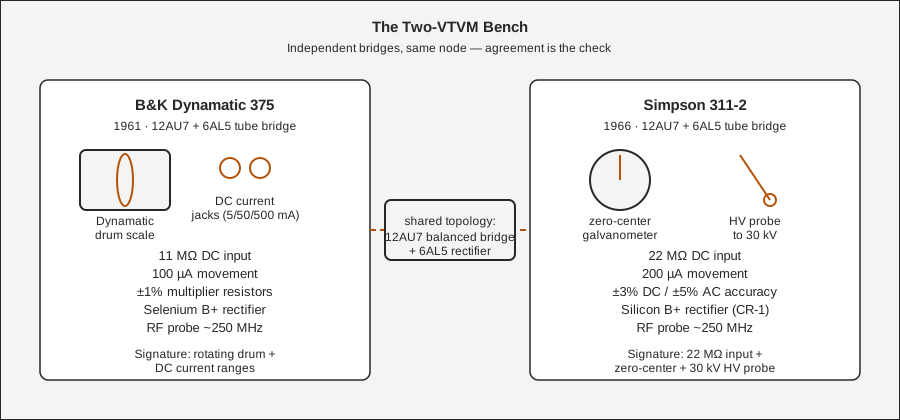
Table 9 — 7. The Two-VTVM Bench: B&K Dynamatic 375 vs Simpson 311-2
| Parameter | B&K Dynamatic 375 | Simpson 311-2 | Detail |
|---|---|---|---|
| Introduced | 1961 | 311: 1958 · 311-2: 1966 | Vol 1 §1 |
| Original price | $89.95 (1961 ad) | [NOT FOUND] | Vol 1 §1 |
| Active devices | 12AU7 (DC bridge) + 6AL5 (AC rectifier) | Same: 12AU7 (DC bridge) + 6AL5 (AC rectifier) | Vol 2 §1-§2 |
| Power-supply rectifier | Selenium rectifier | Silicon diode CR-1, 750 mA | Vol 2 §4 |
| DC input resistance | 11 MΩ, all ranges (1 MΩ probe + 10 MΩ divider — the classic VTVM figure) | 22 MΩ, all ranges (Simpson deliberately doubled it) | Vol 2 §1 |
| AC input resistance | [NOT FOUND] for the 375 specifically | 2.2 MΩ minimum at 60 Hz | Vol 2 §1 |
| Meter movement | Most likely jeweled-pivot D’Arsonval, 100 µA — anti-parallax mirrored scale, iridescent knife-edge pointer; “taut-band” [UNCERTAIN] | Custom D’Arsonval, 200 µA, ~1 kΩ | Vol 3 §5 |
| Signature feature | ”Dynamatic” rotating drum scale — one full-size direct-reading scale lit per range, no multiplying — plus DC current ranges (5/50/500 mA) | 22 MΩ input + zero-center galvanometer mode + 30 kV HV probe | §1.1 above / this row |
| DC volts ranges | 1.5/5/15/50/150/500/1500 V (7) | Identical cascade: 1.5/5/15/50/150/500/1500 V (7) | §2.1 above |
| AC volts (RMS) ranges | Same 7-range cascade | Same 7-range cascade | §2.2 above |
| AC volts (p-p) ranges | Mirrors the RMS cascade (1.5-1500 V p-p) rather than a distinct p-p multiplier set | Separate p-p cascade: 4-4000 V p-p (311-2) | §2.3 above |
| DC current ranges | 5 mA / 50 mA / 500 mA — unusual for a VTVM | None — this is a V/Ω-only VTVM | §2.4 above |
| Ohms ranges | 7 ranges, full-scale 500 Ω-1000 MΩ | 7 decades, ×1-×1M (center-scale 10 Ω-10 MΩ) | §2.5 above |
| Ohms battery | 1.5 V D-size alkaline cell | 1.5 V “C”-cell | Vol 5 §6 |
| Zero-center mode | Not documented — instead a manual DC+/DC− polarity-reversal FUNCTION SELECTOR position | Yes, any DC range (0.75-0-0.75 V on the 1.5 V range) | §3 above |
| RF probe | AV-1A-class demodulator probe, “to 250 MHz” (accessory: AE-1A/PR-38) | 0174 (311-2), 10 kHz-250 MHz | §2.6 above |
| HV probe | [NOT FOUND] — no HV probe documented in the 375’s sources | 0732, 0-30 kV safe (marked to 50 kV), ×100, raises input to 2,200 MΩ | §2.6 above |
| Accuracy | ±1 % multiplier resistors; overall %-of-FS figures [UNCERTAIN] — obscured in the source ad | ±3 % DC / ±5 % AC / ±3° ohms | §1 above |
| Case size | 10½ × 6½ × 4 in | 7½ × 5⅝ × 4½ in | Vol 3 §1 |
| Weight | ~8 lb net | 4½ lb net | Vol 3 §1 |
| Known service gotcha | Pot-to-case grounding (loose shaft nut → dead/erratic meter) | Battery-holder corrosion; 12AU7 needs ≥48 h aging after replacement | Vol 5 §1-§2 / §4 above |
| Bridge type | Balanced bridge, both triode halves of one 12AU7 | Same topology, same tube role | Vol 2 §1 |
Note — Both instruments are built around the exact same active-device pairing — a 12AU7 balanced-bridge DC amplifier and a 6AL5 AC rectifier — which is why they make sense as a cross-check pair rather than two unrelated designs: a systematic bridge-topology error would show up on both meters, while a component-drift error on just one would show up as disagreement between them. Where they differ is exactly where the redundancy pays off: the Simpson’s doubled 22 MΩ input loads a high-Z node less than the B&K’s 11 MΩ, while the B&K’s Dynamatic drum and added DC current ranges cover things the Simpson doesn’t touch at all.
6.8.1 Which one to reach for
Table 10 — 7.1 Which one to reach for
| Situation | Reach for | Why |
|---|---|---|
| Highest-Z node in a tube circuit (grid bias, AVC line) | Simpson 311-2 | 22 MΩ loads the node half as much as the B&K’s 11 MΩ |
| Need a DC current reading | B&K 375 | Only the 375 has DC mA ranges — the Simpson is V/Ω only |
| FM discriminator / balance-point alignment | Simpson 311-2 | Zero-center galvanometer mode is built in; not documented on the 375 |
| Voltage above 1500 V DC | Simpson 311-2 with the HV probe (0732), up to 30 kV | The 375 has no documented HV probe |
| Cross-checking a suspect reading | Both, agreement required | The entire point of the two-VTVM bench — see the callout above |
| Reading a single range fast, minimal squinting at a crowded dial | B&K 375 | The Dynamatic drum shows one full-size scale, no multiplying |
| Suspect a dead/erratic unit before assuming a bad tube | Check the 375’s ZERO/OHMS pot grounding first | The documented “375 woes” failure mode — see §4 step 1 |
6.9 Where the Simpson 260 Fits (for contrast, not comparison)
The Simpson 260 is not a third VTVM on this bench — it’s the loadable 20,000 Ω/V VOM both tube voltmeters exist to out-class on high-Z nodes. On its 1.5 V DC range the 260’s input resistance is only ~30 kΩ (20 kΩ/V × 1.5 V); even on its 500 V range that’s only 10 MΩ — still below the 375’s 11 MΩ on every range, and the 260’s resistance changes range-to-range where the VTVM’s does not. That’s the whole reason a VTVM exists: a passive VOM draws current from the circuit under test to deflect its coil, and on a high-impedance tube grid or bias node that current draw itself changes the voltage you’re trying to read. The 260 stays the right tool for continuity, low-Z circuits, and anywhere its loading doesn’t matter — it just isn’t a stand-in for either VTVM on the nodes this bench pair exists to measure.
6.10 Consumables, Wear Items & What You Cannot Replace
A shopping-list view of §4 and §5, organized by how easy each part is to source today.
Table 11 — 9. Consumables, Wear Items & What You Cannot Replace
| Item | Sourcing difficulty | Notes |
|---|---|---|
| 12AU7 dual triode | Easy — common, cheap, still manufactured/NOS-abundant | Bridge tube; swap freely once pot grounding (§4 step 1) is ruled out |
| 6AL5 dual diode | Easy — common, cheap, still available | AC rectifier tube |
| 1.5 V D-size alkaline cell | Trivial — any hardware/grocery store | Ohms function only; leave it out during storage to prevent leak/corrosion |
| ±1 % film resistors (replacing drifted carbon-comp) | Easy — generic modern part, any electronics distributor | Substitute for drifted R21 (6.8 MΩ), R25 (3.3 MΩ), and other precision-string members |
| Selenium B+ rectifier | Moderate-to-hard — obsolete part; most restorers substitute a modern silicon diode of equivalent forward drop/rating and derate for the voltage difference | Treat any existing selenium stack as a hazardous-materials item first (§5); don’t source a NOS selenium replacement unless originality is the goal |
| DC-AC-Ohms probe (standard, supplied) | Moderate — no confirmed drop-in aftermarket source found in this dive’s research; salvage from a donor unit or fabricate | The wear item most likely to need attention on a well-used unit |
| RF demodulator probe (AE-1A/PR-38, AV-1A class) | Moderate — NOS units surface occasionally (Surplus Sales of Nebraska carried an AV-1A-class part at time of writing) | Accessory, not required for basic V/Ω/mA use |
| ”Dynamatic” rotating drum + indexing mechanism | Effectively unobtainable | Unique to this instrument. If it’s damaged, the only realistic path is a donor 375’s drum assembly. Protect it — see §4 step 6. |
Note — The drum is the one line in this table that changes the calculus on a “parts unit” — if you’re weighing two rough 375s for one good one, the drum condition matters more than tube complement or battery state, because everything else on this list is sourceable and the drum is not.
Sources
- radiomuseum.org — B&K Dynamatic 375 (year, tubes, selenium B+, price, size, schematic + photo set): https://www.radiomuseum.org/r/dynascan_k_dynamatic_375.html
- radiomuseum.org — 1961 advertisement spec block (ranges, 11 MΩ, 100 µA movement, 1½ V battery, ±1 % multipliers, size/price): https://www.radiomuseum.org/images/radio/b_k_dynascan_corp/b_k_dynamatic_375_2105857.jpg
- radiomuseum.org — schematic image (title block “B&K MFG CO MODEL 375 VTVM”, PM-285M-F): https://www.radiomuseum.org/images/schematic-medium/b_k_dynascan_corp/b_k_dynamatic_375_2095388.png
- BAMA manual archive — B&K 375 (bk375.djvu incl. AE-1A & PR-38 probes + 1961 ad): http://bama.edebris.com/manuals/b&k/375
- elektrotanya — “B-K DYNAMATIC-375 TUBE VOLTMETER” service manual, 24 pp PDF: https://elektrotanya.com/b-k_dynamatic-375_tube_voltmeter.pdf/download.html
- Antique Radio Forums — “B&K Dynamatic 375 VTVM woes” (grounding fix, R21 6.8 M / R25 3.3 M / R27, R32 11 k / R30 15 k, battery to E-deck term 12, 12AU7 + 6AL5): https://antiqueradios.com/forums/viewtopic.php?p=1517272 and https://antiqueradios.com/forums/viewtopic.php?p=1517468 and https://www.antiqueradios.com/forums/viewtopic.php?t=3786
- Surplus Sales of Nebraska — B&K RF Demodulator Probe (AV-1A, “to 250 MHz, for most VTVMs”): https://www.surplussales.com/items/99536/bk-rf-demodulator-probe/
- byan-roper.org (Steve Byan) — switchable VTVM probes (1 MΩ isolation-resistor design; B&K PR-43 for the 177, PR-21/100 kΩ for the 277 FET Multimeter): https://www.byan-roper.org/steve/steve-at-play/antique-electronics-and-2/switchable-vtvm-probes.html
- radiomuseum.org — B&K 177 VTVM (~1970, 12AU7 + 6AL5, battery-less ohms): https://www.radiomuseum.org/r/dynascan_precision_model_vtvm_177.html
- elektrotanya — B&K 277 solid-state (FET) multimeter, 1982 manual (confirms the 277 is the later FET/solid-state model): https://elektrotanya.com/bk-precision_277_sollid_state_electronic_multimeter_1982_instr._sm.zip/download.html
- Simpson Electric Co., Operator’s Manual — Vacuum Tube Voltmeter Model 311-2, © 1966 (part 5-110700), for the comparison table in §7: https://www.simpson260.com/downloads/simpson_311-2_user_manual.pdf
- Simpson Electric Co., Operator’s Manual — Vacuum Tube Voltmeter Model 311, © 1958, for the comparison table in §7: https://simpson260.com/downloads/simpson_311-1_user_manual.pdf