Curve Tracers — Overview & Primer · Volume 2
Curve Tracers — Vol 2: A Short History
Tektronix 570 → 575 → 576 → 577 → 370, the tube-tester distinction, and the DIY revival
2.1 Why a history volume at all
The curve tracer did not evolve gradually out of the meter the way a lot of bench gear did. It arrived as a deliberate instrument, from one company, aimed first at vacuum tubes and then — within about two years — retargeted at the transistor just as the transistor started to matter commercially. Almost everything on a modern bench that traces an I-V curve, whether it is a $40,000 semiconductor parameter analyzer or a $50 hobby PCB, is a descendant of that original architecture: a stepped control-terminal generator, a swept main-terminal supply, and an X-Y display that paints one curve per step. Vol 1 laid out that architecture in the abstract. This volume traces where it actually came from, pins the dates down against the record, draws the line between a curve tracer and a tube tester (a distinction the vintage-audio world blurs constantly), and follows the thread forward to the DIY designs that put the instrument back within reach — the five of which are their own dives in this hub.
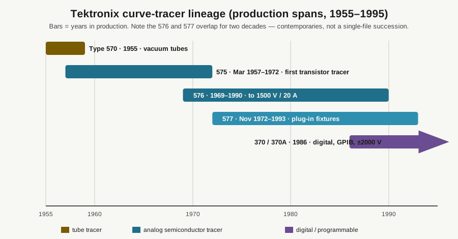
The dates below matter, because the secondary sources disagree with each other and with a fair amount of hobby folklore. Where a year is given here it is the verified one, and where two models are commonly assumed to be strict successors when they were in fact contemporaries, that is called out explicitly.
2.2 Tektronix invents the category
The curve tracer as a self-contained bench instrument is essentially a Tektronix invention, and it arrived in two waves — first for tubes, then for transistors.
2.2.1 The Type 570: a tube tracer (1955)
The Tektronix 570 came first, introduced in 1955. It was Tek’s first curve tracer, and it was built for vacuum tubes. The concept grew out of John Kobbe’s work off the 540-series oscilloscope line, and the instrument does exactly what Vol 1’s tube figure describes: it sweeps the plate (anode) voltage from zero up through hundreds of volts while stepping the control grid through a staircase of bias voltages, and it displays plate, screen, or grid current against plate (or grid) voltage on its round CRT. It carries dedicated provisions for the screen (second grid) so that pentodes and tetrodes can be biased properly rather than just triode-connected, and a front-panel pointer voltmeter lets the operator watch the DC and heater supplies while a family of four to twelve steps is drawn.
The point worth holding onto is that the 570 already had the entire architecture the rest of this category inherits — step generator, sweep supply, X-Y display — a full year before the transistor version existed. What changed afterward was the terminal names and the voltage envelope, not the idea. Sweep a main-terminal voltage, step a control-terminal bias, plot current against voltage: the 570 is the 1955 proof that a picture of the whole operating surface beats a single spot-reading, applied to valves.
2.2.2 The Type 575: the first transistor tracer (March 1957)
The Tektronix 575 followed in March 1957 and pointed the same idea at the newly important transistor. It is Tektronix’s first semiconductor curve tracer, and it defined the first-generation transistor-lab instrument. Its structure decomposes into the three blocks Vol 1 named: an X-Y display, a base step generator that builds the staircase of base drive, and a collector sweep supply that ramps the collector voltage across each step. Feed it an NPN and it draws the fan of collector-current curves, one per base-current step; the vertical spacing between adjacent curves is the current gain, read straight off the screen (Vol 4 works through that).
Two facts about the 575 tend to surprise people, and both are worth stating plainly.
First, the date. A “575 = 1955” figure circulates in some hobby writeups; it is a conflation of the two models. The 1955 machine is the 570 (tubes); the 1957 machine is the 575 (transistors). The 575 was produced from 1957 to 1972, when the 576 took over its role, and across that fifteen-year run it became the wrinkle-finish box with the round CRT and the rotating device sockets that you see in almost any photograph of a 1960s semiconductor lab.
Second — and this is the one that catches everybody — the 575’s own internals are vacuum tubes. It is a tube-based instrument built to characterize transistors. There is no contradiction here once you separate the device under test from the technology of the tester: in 1957 the reliable way to build a precise, wide-range analog sweep-and-step generator with a good CRT was with tubes, so that is what Tektronix used, and the fact that the thing on the socket was a germanium transistor did not change the design of the box driving it. This is the cleanest early illustration of a theme that runs through the whole category: the tester’s internal technology and the DUT’s technology are independent choices.
On the envelope: in its original form the 575’s collector sweep reached roughly 0–200 V peak on its low-current range, trading down to 0–20 V at the high-current (to ~20 A) end, inside a maximum dissipation to the DUT of about 200 W. A later factory modification (Mod 122C) extended the high-voltage range to about 400 V. Treat the exact 20 A / 400 V mod figures as spec-sheet-dependent — different production variants and options shift them — but the shape of the trade-off is the permanent lesson: high voltage and high current live on different range-switch positions, never simultaneously. You cannot get 200 V and 20 A at once; you get one or the other depending on where the range switch sits. That trade recurs on every model that follows, and misreading it is how people talk themselves into believing a tracer can dissipate far more than it can.
2.3 The classic bench instruments: 576 and 577
If the 575 is the instrument that established the category, the 576 and 577 are the instruments that most working engineers actually remember, and they are usually misremembered as a simple old-model / new-model pair. They were not. They overlapped in production for roughly two decades and answered slightly different bench needs.
2.3.1 The Type 576: the machine people picture (1969)
The Tektronix 576, introduced in 1969, is the unit most people have in mind when they say “curve tracer.” It kept the built-in ~10 × 10 cm CRT with an internal, parallax-free graticule, but it added an alphanumeric readout that printed the important front-panel scale factors — volts per division, current per division, and the per-step value — directly onto the screen. That sounds like a small thing; it is not. It means a photograph of the display is self-documenting: you can read the trace and the settings that produced it off a single image, which is exactly what you want when you are logging a matched pair or filing a failure-analysis photo. It handled the full semiconductor menagerie — bipolars, JFETs and MOSFETs, SCRs, triacs and diacs, ordinary diodes and rectifiers, Zeners, and tunnel diodes.
Its envelope is where the “vintage tracers go to ~1.5 kV” figure comes from, and it repays reading carefully. The 576’s collector supply reaches 1500 V, but only on its highest-voltage / lowest-current range; the four switchable ranges are approximately:
- 15 V / 10 A — the high-current range, for saturation and low-voltage power work;
- 75 V / 2 A;
- 350 V / 0.5 A;
- 1500 V / 0.1 A — the high-voltage range, at only 100 mA.
Peak current tops out around 20 A (on the 15 V range), and there is a maximum-power ceiling of about 220 W to the DUT that caps what any range can actually deliver into a load. So the honest way to state the capability is as a set of range ceilings, not as a single V×I number: you get 1500 V or 20 A, on different switch positions, and never the product of the two. Reading “1500 V, 20 A” as a simultaneous rating is the classic misuse of a tracer spec sheet, and it is worth internalizing here because Vol 4’s discussion of range ceilings and Vol 5’s buy-vs-build advice both depend on getting it right.
The 576 stayed in production through about 1990 and remains a genuine workshop favorite — the analog display is fast, legible, and forgiving, and a working 576 still does real bench work today (Vol 5).
2.3.2 The Type 577: the plug-in-fixture companion (November 1972)
The Tektronix 577, introduced in November 1972 and produced through 1993, is where the “successor” story falls apart. It is not the 576’s replacement; it is a lighter, more flexible companion built around interchangeable plug-in test fixtures rather than a fixed test station. A 577 mainframe takes a 177 fixture for discrete devices or a 178 fixture for linear ICs — regulators, op-amps and the like — which made it well suited to production test and teaching benches where the device style changed often. It also came in two display flavors: the 577/D1 with a storage CRT (so a slow or single-shot trace could be held on-screen) and the 577/D2 without storage.
Its high end reaches a collector sweep of about 1600 V at 40 mA, with vertical current sensitivity spanning an enormous range — from 0.2 nA/div for leakage measurements up to 2 A/div for power devices. That 0.2 nA/div figure is the one to notice: it is what lets a tracer show sub-nanoamp reverse-leakage and gate current, the small-signal end of the same instrument that can also push amps.
The chronology is the whole point. The 577 launched in 1972, seventeen years before the 576 left production in 1990, and it kept going until 1993. So for roughly two decades the 576 and the 577 were contemporaries on the same price list — pick the fixed-station 576 for a permanent characterization bench, pick the fixture-based 577 where flexibility mattered — and both were eventually replaced by the digital 370-series, not by each other. The timeline figure above shows the overlap directly: two long bars running side by side, not a baton pass.
2.3.3 The digital successors: 370 and 371 (1986)
The line’s true digital successors were the Tektronix 370 and 371, which arrived in 1986. They replaced the analog CRT with a digital storage display and added programmable, GPIB-controlled operation, so a tracer could finally sit inside an automated test setup and hand its measurements back to a controller. Under that digital skin the fundamental method is unchanged — step a control terminal, sweep the main terminal, plot current against voltage — but the range pushed further out, to about ±2000 V and ±20 A, and the instrument gained stored setups and captured data (the 370 used a bubble-memory cassette; the 370A and 370B moved to floppy disk). These are the units that finally ended the classic analog line, and 370-series machines — along with surviving 576s and 577s — are the vintage iron people still hunt for (Vol 5).
2.4 The distinction that matters: curve tracer vs tube tester
It is worth stopping on a confusion that shows up constantly in the vintage-audio world, because getting it wrong leads people to buy the wrong instrument: a tube tester is not a curve tracer. They answer different questions, and this hub deliberately keeps both kinds precisely because the jobs are different.
A tube tester — the emission testers and the better mutual-conductance (transconductance, gm) testers such as the Hickok and Heathkit machines covered elsewhere in this hub — applies a small, fixed set of bias voltages and reports essentially one number per test: emission current, or transconductance in micromhos (µmhos) — equivalently microsiemens — at a single operating point. A gm tester is genuinely useful: transconductance is the slope of plate current versus grid voltage at that bias, and it predicts, at that point, how hard the tube will pull. That is enough to sort “good / weak / shorted / gassy,” which is most of what a service bench needs. But a tube’s characteristic is curved and nonlinear across its whole operating range, and matching two tubes at one bias point does not guarantee they track each other across the swing they actually work over. Two 12AX7 sections can read identical gm at one point and diverge noticeably at the extremes of a large signal swing.
A tube curve tracer — the 570, or a modern pulsed-HV design like the uTracer NXT or eTracer dives in this hub — draws the whole plate family (Vol 1’s tube figure). You can read plate current at any plate voltage for any grid bias, lay the curves against the datasheet, and match tubes across their entire operating surface rather than at a single spot. Transconductance is then just the local vertical spacing of the curves at whatever bias you care about, and you can see the Early-effect-like plate-resistance slope, the onset of grid current, and the knee where the tube runs out of plate voltage — none of which a single-number tester reveals.
So the trade is the same one that runs through all of test equipment: the curve tracer is the strictly more informative instrument, and the tube tester is the faster, cheaper, go/no-go one. For sorting a box of pulls, the tester wins on throughput. For matching an output-stage quad or chasing why one channel distorts, only the curve does the job. Note one more time the terminology trap this volume opened with: the characteristic-curve tracer here is a different animal from the go/no-go tube tester, and — just to keep everyone on their toes — the semiconductor 575 is itself internally a vacuum-tube instrument. Device technology and tester technology are independent; keep them separate in your head and none of this is confusing.
2.5 Heathkit brings it to the hobby bench
Tektronix iron was expensive laboratory equipment, and for most of the 1960s that put semiconductor curve tracing out of reach of the hobbyist and the small service shop. Heathkit closed that gap with the IT-1121 semiconductor curve tracer, introduced in the early 1970s, and its later, electrically identical restyle the IT-3121. The two differ only cosmetically — same circuit, different front panel and era-appropriate styling — so anything said about one applies to the other, and the Heathkit IT-3121 dive in this hub treats them together.
The IT-1121 / IT-3121 is an add-on design, and understanding that is the key to the machine: it has no CRT of its own. It generates the base-current staircase and the collector sweep internally and hands the resulting X and Y signals to your oscilloscope, run in X-Y mode, which is how it stayed affordable — the display was the most expensive part of a self-contained tracer, and Heathkit simply reused the scope you already owned. It handles NPN and PNP bipolars, N- and P-channel FETs, and diodes including Zeners and tunnel diodes, with a collector envelope of about ±200 V and up to ±1 A, the same high-current-or-high-voltage trade the Tek iron shows, scaled down for the bench — you get the high voltage or the high current, not both at once. From those traces you can read DC and AC beta, saturation voltage, breakdown, and linearity, and — the reason many people bought one — match complementary pairs for audio output stages.
Circuit-wise it is a thoroughly 1970s analog design: on the order of eighteen transistors, a handful of 741 op-amps, and a single TTL counter clocking the staircase. That simplicity is exactly why it remains repairable, hackable, and a favorite restoration target half a century later — there is nothing in it a patient builder cannot trace, fix, or improve, and the IT-3121 dive documents both the restoration and a set of modern modifications to it. Envelope-wise the IT-3121 sits right where a hobby bench wants it: ±200 V / 1 A covers the overwhelming majority of small-signal and modest-power semiconductors without the lethal 1.5 kV of the big Tek units.
2.6 The modern DIY revival
For a couple of decades after the classic Tek line wound down, curve tracing meant one of two things: hunting for vintage iron, or spending real money on a semiconductor parameter analyzer. Then the hobbyist and open-hardware community brought the instrument back — and, tidily, it came back split along the same two-family line as the originals: tube tracers and semiconductor tracers.
2.6.1 The tube side: pulsed high-voltage tracers
On the tube side, the enabling trick is the pulsed high-voltage technique that Vol 3 works through in detail. The problem with a continuous tube tracer is dissipation: holding a power tube at several hundred volts and tens of milliamps means dissipating real wattage continuously, which demands a bench full of regulated HV supplies and heat-sinking. The pulsed approach sidesteps it entirely — charge a reservoir capacitor to the target voltage, apply the plate and screen voltages as a brief pulse (on the order of a millisecond), sample the current during the pulse, and let the tube cool between points. Average dissipation stays tiny, so the whole HV section shrinks onto a small PCB.
Ronald Dekker’s uTracer family is the reference example, and this hub carries the current models as their own dives. The lineage ran through the now-obsolete uTracer3 to two current designs: the uTracer6 dive — Dekker’s kilovolt model, reaching 0–1000 V so it can characterize sweep, beam-power, and small transmitter tubes — and the uTracer NXT dive, a next-generation Dekker architecture (in the 450–500 V class) that is the current mainstream DIY tube tracer. Alongside them sits the eTracer dive: a commercial pulsed-HV tube tracer from Essues (Chris Chang) in Taiwan — an independent design inspired by the uTracer, not a Dekker product — reaching 0–750 V with software curve plotting and SPICE-model export. Getting those envelopes and origins straight matters when you reach Vol 5’s buy-vs-build comparison: uTracer6 is the DIY kilovolt option (Dekker, 0–1000 V), uTracer NXT is the current DIY mainstream (Dekker, 450–500 V), and eTracer is the commercial 0–750 V rival (Essues, Taiwan).
2.6.2 The semiconductor side: modern step-and-sweep
On the semiconductor side, the revival is Paul Versteeg’s open-source VBA Curve Tracer, named for its three principal contributors — Versteeg, Bud Bennett, and Mark Allie. It is a fully analog, well-documented, build-it-yourself revival of the classic step-and-sweep semiconductor tracer, plotting onto an ordinary oscilloscope in X-Y mode exactly as the Heathkit did. Versteeg’s 2017 prototype grew into a multi-board design with published schematics and files, and it is explicitly aimed at being the instrument you build when the school or shop’s aging 576 or 577 finally dies beyond economical repair. The VBA Curve Tracer dive covers it in full; note that it is fully analog — no microcontroller in the signal path — which is a deliberate choice that keeps the traces fast and the design transparent.
2.6.3 The arc
So the shape of the whole history is clean. Tektronix invented the category for tubes with the 570 (1955), retargeted it at transistors with the 575 (1957), refined it into the classic analog bench with the overlapping 576 (1969) and 577 (1972), and finally digitized and programmed it with the 370 / 371 (1986). Heathkit democratized the semiconductor version for the hobby bench with the IT-1121 / IT-3121 (early 1970s). And the modern open-hardware community rebuilt both halves — pulsed-HV tube tracers (the uTracer6, uTracer NXT, and eTracer dives) and step-and-sweep semiconductor tracers (the VBA dive) — as designs anyone can build or buy at bench prices. Five of those instruments are their own dives in this hub, and Vol 5 lays them side by side against the vintage Tek iron and the Heathkit as buy-vs-build options.
Vol 3 opens up how each of these actually works — the semiconductor step-and-sweep, the pulsed-HV tube technique, and the humble octopus — control by control.
Date note. Per TekWiki, the Type 570 (vacuum-tube tracer) was introduced in 1955 and the 575 (transistor tracer) in March 1957; this volume uses those verified dates and treats the “575 = 1955” claim found in some secondary sources as a conflation of the two models. The 576 dates to 1969 and stayed in production to about 1990; the 577 to November 1972, produced through 1993 — so the two were contemporaries, not strict successors, both later replaced by the 370 / 371 (1986). The ~1.5 kV figure for the flagship analog tracers is a high-voltage-range ceiling (576: 1500 V at 0.1 A; 577: 1600 V at 40 mA), never a simultaneous V×I capability, since maximum voltage and maximum current live on different range-switch positions.