Curve Tracers — Overview & Primer · Volume 5
Curve Tracers — Vol 5: Buy vs Build
Vintage Tek iron, the Heathkit, scope adapters, and the modern DIY designs — and which to reach for
The reading skill from Vol 4 is portable across every tracer ever built. Beta is still collector-current spacing divided by base-current step; gm is still the slope of the transfer curve; the Early effect is still that gentle upward tilt in the active region; a breakdown corner is still a breakdown corner. None of that cares what draws the picture. What changes between instruments is the box — its envelope, its ergonomics, its safety margins, its repairability, and how much of your bench it occupies. This volume lays out the landscape as it stands today: five practical routes to a working curve tracer, what each one buys you, what each one costs you, and which to reach for when you already know what you want to test. Where a route corresponds to one of the specific instrument dives in this hub, it is named so you can follow the cross-link for the deep detail this primer deliberately leaves to the per-instrument volumes.
One framing note before the routes. “Buy vs build” is not really a binary on this bench — it is a spectrum, and this hub deliberately sits on both ends of it at once. It keeps and restores vintage Tektronix iron and it builds the modern DIY tracers, because the DIY-vs-buy duality runs through every instrument class here, not just curve tracers. The right answer is usually “own more than one,” because the cheapest tool (an octopus) and the most capable tool (a 576 or a DIY pulsed-HV tube tracer) do genuinely different jobs and cost wildly different amounts.
5.1 Route 1 — vintage Tektronix iron (575 / 576 / 577 / 370)
5.1.1 What you get
A self-contained laboratory instrument: its own CRT, its own step generator and sweep supply, its own calibrated scale factors, and — on the 576 and later — an alphanumeric readout that prints the front-panel scale factors right on the screen so a photograph of a trace is self-documenting. This is the genuine article, the machine that defined the category (Vol 2), and its build quality has already survived half a century of benches.
The lineage, with the dates that matter:
- The Tektronix 575 (introduced March 1957, produced to 1972) is the first-generation transistor tracer — the wrinkle-finish box with the round CRT and rotating device sockets. Worth remembering when you fix one: the 575 traces transistors but its own internals are vacuum tubes. Its collector sweep reached roughly 0–200 V peak in standard form (0–400 V with the Mod 122C option), up to about 20 A on the high-current range, within a ~200 W dissipation limit. It is the earliest, cheapest, and most limited of the family, and it is a tube instrument you will be maintaining as tube gear.
- The Tektronix 576 (introduced 1969, produced to 1990) is the machine most people mean when they say “curve tracer,” and the one most restorers chase. Its envelope is formidable: collector voltage to 1500 V across four switchable ranges, up to ~20 A peak on the high-current range (whose continuous rating is 10 A at 15 V), within a 220 W limit to the device under test.
- The Tektronix 577 (introduced November 1972, produced to 1993) is the lighter, plug-in-fixture companion — not a replacement for the 576 but its contemporary. The two sold alongside each other for nearly two decades. The 577 uses interchangeable plug-in display units (a D1 storage-CRT version, a D2 non-storage version) and a family of test fixtures (177 for discretes, 178 for linear ICs). Its highest sweep range reaches 1600 V at 40 mA, with vertical current sensitivity from 0.2 nA/div up to 2 A/div.
- The digital 370 / 370A (introduced 1986) replaced the analog CRT with a digital storage display and added GPIB programmability, pushing the envelope to ±2000 V / ±20 A. This is the modern, automatable end of the line; both the 576 and 577 were eventually replaced by the 370/371 series, not by each other.
5.1.2 The one number everyone quotes wrong
You will see “~1.5 kV curve tracer” attached to the 576 constantly, and it is true — but it is a range ceiling, not a simultaneous capability. The 576’s four ranges are 15 V / 10 A, 75 V / 2 A, 350 V / 0.5 A, and 1500 V / 0.1 A. Maximum voltage lives on one range-switch position; maximum current lives on a different one. You get 1500 V only at 0.1 A, and the biggest currents — ~10 A continuous on the 15 V range, up to ~20 A peak-pulse — only down at 15 V. The instrument cannot do 1500 V and that kind of current at the same time — even at the 20 A peak figure that would be 30 kW into a discrete device, which is absurd on its face. The envelope is a descending staircase, and the top-right corner is empty.
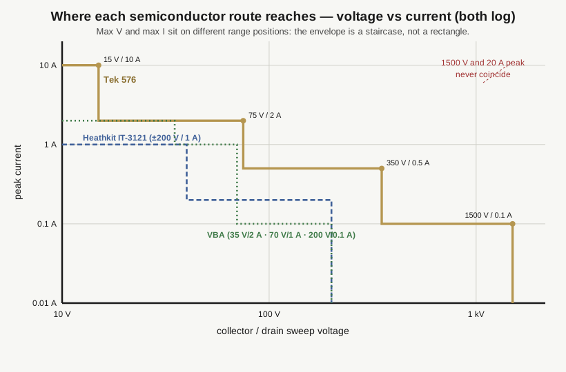
The physics behind the staircase is the 220 W dissipation limit doing its job: every range is a constant-power (or lower) corner of a V×I hyperbola, so as you buy more voltage you necessarily give up current. This is exactly the “range ceiling” trap from Vol 4 — read the envelope as a set of corners, never as a rectangle, and never assume the high-voltage number is available at your working current.
5.1.3 The catch
These are big, heavy (a 576 is a two-hands-and-a-cart 20 kg-class instrument), power-hungry, and now decades past their design service life. The failure list is predictable: aging electrolytic capacitors in the supplies, a CRT that dims and can go soft, multi-deck range switches with tarnished contacts, relays, and — because these are high-voltage instruments — real shock hazard behind the panel even after the mains is pulled, since the collector-supply and CRT circuits hold charge. Documentation and calibration are on you; a dead one with a bad CRT or an unobtanium custom transformer can become an expensive doorstop, and prices have climbed steadily as these became collectible rather than surplus.
Reach for vintage Tek iron when you want the no-compromise, self-contained, calibrated instrument, you value the finished object, and you are genuinely comfortable maintaining fifty-year-old high-voltage analog gear. The whole restoration ethos of this hub lives here — recap it, re-cal it, and it will outlast most of what is on the bench beside it.
5.2 Route 2 — the Heathkit IT-1121 / IT-3121
5.2.1 What you get
A far smaller, simpler dedicated semiconductor curve tracer that hands its X and Y signals to your own oscilloscope in X-Y mode instead of carrying a CRT. Heathkit put semiconductor curve tracing on the hobby bench with the IT-1121 and its electrically identical, cosmetically restyled successor the IT-3121 — the two differ only in appearance. Collector voltage reaches about ±200 V and current about 1 A, split across two ranges (roughly 40 V / 1 A and 200 V / 200 mA), with a base-current staircase covering about 0.002–10 mA/step. That is enough to read DC and AC beta, the saturation knee, breakdown, and linearity, and — the job it is quietly best at — to match complementary pairs by overlaying two devices’ families on the same screen.
Under the lid it is honest 1970s analog: on the order of eighteen transistors, five 741 op-amps, and a single TTL counter clocking the staircase. That simplicity is the whole point — there are no ASICs, no firmware, no custom parts you cannot source. It is genuinely repairable and modifiable on the bench, which is why it still has an active following. Working units traded around $200–$300 in the early 2020s, an order of magnitude below vintage Tek iron.
5.2.2 The catch and the upgrade path
As built, it has three real limits. First, it steps only negative gate voltage, so it traces JFETs and depletion-mode parts but not enhancement-mode MOSFETs, which need a positive gate offset to turn on at all. Second, its drive is pulsating DC, not true AC, so it does not sweep both polarities the way a full Tek does. Third, it stops at 200 V, well short of the breakdown voltages of many power parts.
The DIY community has answered all three. The djerickson redesign around the IT-3121/IT-1121 adds a positive gate offset so enhancement MOSFETs finally trace, swaps the fragile multi-deck rotary switches for relay plus microprocessor control, replaces the hardware polarity switches with dual 12-bit DACs for software-selectable positive/negative drive, and digitizes the display through ADCs — with a stated goal of pushing the voltage envelope up (“400 V good, 1 kV great”). The Heathkit IT-3121 dive in this hub covers both the stock instrument and these modifications in detail.
This is the route when you want a real, dedicated, three-terminal semiconductor tracer without vintage-Tek bulk or price, and — the prerequisite — you already own an X-Y-capable scope to be its display.
5.3 Route 3 — the scope adapter and the octopus
5.3.1 Scope curve-tracer adapters
The Heathkit above is itself an example of the broader category: a scope adapter is a small box that generates the step-and-sweep drive and uses your oscilloscope as the display in X-Y mode. If you already own a good scope, this is the cheapest way into real three-terminal curve tracing, because you are not paying for a CRT and its high-voltage supply a second time. The modern DIY designs in Route 4 (the VBA especially) are scope adapters in this same sense.
5.3.2 The octopus
The octopus (Vol 3) is the cheapest and fastest route of all, and every bench should have one. It is barely a circuit: a filament/isolation transformer, one series resistor, and two clip leads onto your scope’s X and Y inputs in X-Y mode. It drives a low AC test voltage — typically around 1 V at under 1 mA — across an unknown two-terminal device and plots device voltage (X) against current (Y). Each part type draws a distinct Lissajous signature: a horizontal line is an open, a vertical line is a short, a sloped line is a resistor, an ellipse is a capacitor or inductor, and a backward-L knee is a diode. This is Analog Signature Analysis (ASA), and the name “octopus” comes from all the test leads.
What the octopus will not give you is a β or gm family — it has no stepped third terminal, so it cannot bias a base or gate. What it does give you is unbeatable for in-circuit fault finding: because the test voltage is low and the board is unpowered, you can probe components in place, without desoldering and without risk of powering up a fault, and compare a suspect board’s signatures against a known-good reference to spot shorts, opens, leakage, and blown junctions in seconds. It complements a real tracer rather than replacing it — the octopus finds the dead part fast, and the tracer then characterizes its replacement properly.
5.4 Route 4 — the modern DIY designs
The DIY revival split along exactly the same two-family line as the originals (Vol 2): pulsed-HV tracers for tubes, and step-and-sweep tracers for semiconductors. Each of the designs below is its own deep dive in this hub; the envelopes here are the summary, and the per-instrument dive is where the build detail lives.
5.4.1 For tubes — the pulsed-HV designs
These fit a several-hundred-volt tube characterizer onto a small board using the pulsed-HV technique from Vol 3: rather than dissipate hundreds of volts continuously, the instrument charges a reservoir capacitor, applies the plate and screen voltages as a brief pulse (on the order of a millisecond), samples the current during the pulse, and lets the capacitor recharge before the next step. A tiny board can therefore characterize a power tube without a bench full of regulated high-voltage supplies, and the curve families are plotted in host software on a PC.
- The uTracer6 is Ronald Dekker’s high-voltage generation — the kilovolt model. It covers roughly 0 to 1000 V at up to 1 A on the anode and screen supplies, with a 0 to −100 V grid supply (and an optional positive-grid capability), which is enough to characterize serious sweep, beam-power, and transmitter tubes that the lower-voltage designs cannot reach. This is a distinct high-voltage model, not a revision of the older uTracer3. The uTracer6 dive covers the build.
- The uTracer NXT is Dekker’s newer, clean-sheet design and the current mainstream of the line — a more compact, community-enclosed package targeting roughly 450–500 V on the anode/screen supplies, which comfortably covers the receiving and small power tubes that make up most of what crosses a restoration bench. The uTracer NXT dive carries the up-to-date architecture and specifications; confirm the current build figures there before you rely on them.
- The eTracer is a closely related pulsed-HV tube tracer from Essues (Taiwan) — an independent commercial design in the same technical lineage, not a Dekker product. It reaches a higher anode voltage than the classic uTracer3, roughly 0 to 750 V, with a grid range of about 0 to −160 V, and it ships as a kit plus host software. The eTracer dive covers it as the commercial pulsed-HV option in this hub.
For matching and characterizing tubes, any of these three does something no tube tester can (Vol 2): it draws the whole plate family instead of reducing the tube to a single gm number, so you can match across the operating surface, not at one bias point.
5.4.2 For semiconductors — the VBA Curve Tracer
The VBA Curve Tracer — named for its authors, Versteeg, Bennett, and Allie — is an open-source, thoroughly documented, fully analog step-and-sweep semiconductor tracer that plots onto an ordinary oscilloscope in X-Y mode through BNC X and Y outputs. It handles two- and three-terminal parts: BJTs, JFETs, MOSFETs, and Darlingtons. It offers three selectable ranges — roughly 0–35 V @ 2 A, 0–70 V @ 1 A, and 0–200 V @ 100 mA — and, crucially, provides both stepped-current and stepped-voltage drive, so it does the enhancement-MOSFET job the stock Heathkit cannot (a MOSFET wants a stepped gate voltage, not a stepped base current). It is explicitly designed as the instrument you build when a lab’s or school’s aging 576/577 finally dies and cannot be repaired — a modern, repairable, fully understood replacement for the classic bench tracer. The VBA Curve Tracer dive covers the build.
5.5 Choosing — a short decision guide
Match the tool to the device family first, then to your tolerance for bulk, price, and maintenance:
Table 1 — Match the tool to the device family first, then to your tolerance for bulk, price, and maintenance
| If you mainly test… | Reach for | Why |
|---|---|---|
| Vacuum tubes (matching, characterization) | uTracer6 / uTracer NXT / eTracer (DIY, pulsed-HV) | Small, pulse-safe, host-side plots, full plate families a tube tester cannot give — NXT for receiving/small-power tubes, uTracer6 for kilovolt sweep/transmitter tubes |
| Vacuum tubes, and you want the original iron | Tektronix 570 | The genuine 1955 tube tracer, if you can find and maintain one |
| Transistors / diodes / FETs, dedicated instrument, on a budget | Heathkit IT-3121 or VBA Curve Tracer | Real step-and-sweep families onto your own scope; VBA adds the stepped-voltage drive for enhancement MOSFETs |
| Transistors, no-compromise self-contained lab instrument | Tektronix 576 / 577 / 370 | Built-in calibrated CRT, wide staircase envelope to ~1.5 kV / ~20 A (on separate ranges) — at the cost of size, price, and upkeep |
| Dead-board fault finding, in-circuit | An octopus V/I signature tester | Fast ASA against a known-good board, unpowered, no desoldering |
And the buy-vs-build question itself: buy vintage iron when you value the finished, calibrated, self-contained instrument and you enjoy restoration; build a DIY design when you want a modern, documented, repairable instrument you understand top to bottom — and, for tubes especially, when you want the compactness and pulse-safety that only the modern pulsed-HV designs offer. This hub does both on purpose: it restores the vintage gear and builds the DIY tracers, because owning the octopus, the dedicated semiconductor tracer, and the tube tracer together costs less friction than trying to force one instrument to cover all three jobs.
Whichever route you take, the reading skill is the one from Vol 4 — the box just changes. Follow the cross-links into the eTracer, uTracer6, uTracer NXT, Heathkit IT-3121, and VBA Curve Tracer dives for the instrument-specific detail this primer intentionally leaves to them.