eTracer · Volume 1
eTracer — Vol 1: Overview — What the eTracer Is
A commercial pulsed-HV tube curve tracer from Essues (Taiwan), and why it earns bench space
1.1 The one-sentence version
The eTracer is a PC-controlled, pulsed-high-voltage vacuum-tube curve tracer: you plug a tube into it, and instead of a single good/bad verdict it draws you the full family of plate-current curves and hands back the tube’s transconductance (gm), amplification factor (mu), and plate resistance (rp). It is a commercial, fully assembled product designed and sold by Chris Chang of Essues Co., Ltd. in Taiwan, introduced in late 2017. It is not a solder-it-yourself kit, and it is not a Ronald Dekker design — it is an independent competitor that was inspired by, but shares very little with, Dekker’s uTracer.
Those two “not” clauses matter enough that this whole volume is built around getting them right up front, because both are easy to get backwards and I have seen both stated wrong.
1.2 What problem it actually solves
A vacuum tube is a nonlinear device. Its plate current is a function of at least two controlled voltages at once — plate voltage (Vp) and grid bias (Vg) — and for a pentode you add screen voltage (Vg2) as a third. What you really want to know about a tube is not one number but a surface: how plate current behaves across a grid of plate and grid voltages. Plot Ip against Vp for a set of stepped grid biases and you get the classic curve family. From that surface you can read everything a designer or a matcher cares about: the local slope along a curve gives you plate resistance rp, the vertical spacing between curves at fixed Vp gives you transconductance gm, and their product gives you mu.
The obvious way to measure that surface is to apply steady DC to the tube at each operating point and read the current. The problem is that steady DC forces you to build a benchtop HV supply that can continuously deliver the full plate voltage and current, and — worse — it dissipates real power in the tube the entire time you dwell on a point. If you want to explore a tube out toward the interesting corners of its envelope, continuous operation either cooks the tube or forces you to stay timidly inside its rated dissipation. A continuous-DC tracer is bulky, expensive, and self-limiting.
The pulsed approach sidesteps all of that, and it is the reason a device the size of a paperback can characterize power tubes.
1.3 The “flash-camera” trick, at a high level
The eTracer does not hold the tube at each operating point. It flashes it.
A switched-mode supply charges a reservoir capacitor up to the target plate voltage. Then a switch connects that charged capacitor onto the tube’s plate for a brief measurement pulse. During the pulse the instrument samples the plate current, then the switch opens, the tube goes dark, and the reservoir capacitor recharges for the next bias point. Essues’s own documentation reaches for the camera-flash analogy explicitly: you store energy in a capacitor and dump it in a controlled burst rather than running a continuous floodlight.
Two consequences fall straight out of this:
- The measurement pulse is short. In the eTracer it runs 500 microseconds to 5 milliseconds, sequenced by an on-board micro-controller. This runs from hundreds of microseconds up into the milliseconds — far longer than the “tens of microseconds” one might assume — a real, deliberate on-time long enough to let the tube settle and the current be sampled cleanly, but short enough that average dissipation stays low.
- You can push a tube past its continuous rating without destroying it. Because the tube only ever sees full plate conditions for a few milliseconds at a time with long cool-down between pulses, the average power stays modest even while the instantaneous operating point ranges out to places continuous DC could never safely dwell.
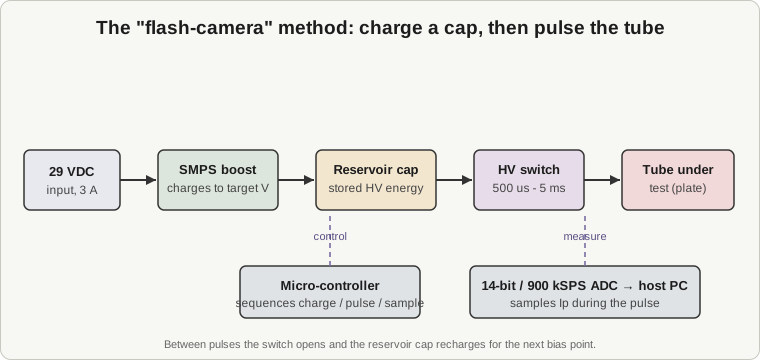
The current sampling during that pulse is done by a 14-bit, 900 kSPS ADC — a genuinely capable converter for this job, and one of the specs that separated the eTracer from the tracers it was competing with in 2017. The detailed hardware — the dual reservoir-cap rails, the exact SMPS topology, the filament and grid supplies, the protection — is Vol 3’s territory; here it is enough to hold the shape of the idea: charge a cap, switch it onto the tube, sample the current on the fly, recharge, repeat.
1.4 What the box actually is
Some concrete framing so this stays grounded in the physical object on the bench:
- It is a commercial, assembled product. The eTracer ships as a fully assembled, tested, and calibrated surface-mount PCB — not a bag of parts you reflow yourself, and not a publish-the-Gerbers open-hardware project. The board is roughly 21 cm x 15 cm. What the buyer does is integrate that board into a chassis and wire up the tube sockets and connectors. That build-out — chassis, sockets, HT wiring, the poorly-marked PSU polarity trap — is Vol 5’s subject, but the point for orientation is that this is a product you buy, not a project you fabricate.
- The host is a PC. The instrument is driven by host software written in Python (using NumPy, SciPy, and Matplotlib), packaged and licensed for Windows, and known to run under Wine on Linux. It is the software that owns the test modes (Full Scan, Corners), the curve display, and the parameter extraction. Vol 4 covers operating it in detail.
- It measures and it models. Beyond drawing curves, it reports quiescent current, gm, mu, and rp, exports measured data to text, CSV, and PDF, saves curve images, and — the part that earns it real credibility — can export a SPICE model of the tube, compatible with Derk Reefman’s ExtractModel workflow. That last capability is what makes it a design tool and not just a sorting tool.
1.5 Why it earns bench space alongside the other tube testers
Jeff’s tube bench already has instruments that answer is this tube any good? The Supreme Instruments 385 is an emission tester — it tells you good, weak, or bad. The Heathkit TT-1 is a dynamic mutual-conductance tester — it gives you a single gm number in micromhos against a roll-chart reference. Both are fast, both are the right tool for triage, and both stop exactly where the interesting questions begin.
The eTracer answers a different question: what does this tube actually do, across its whole operating range? That is the difference between a verdict and a portrait. When you are matching a quad of output tubes, characterizing a bin of NOS finds, or building a SPICE model to simulate a circuit before you wire it, one gm number at one operating point is not enough — you need the curve family and the extracted parameters. The eTracer produces those, and then hands you a SPICE model on top.
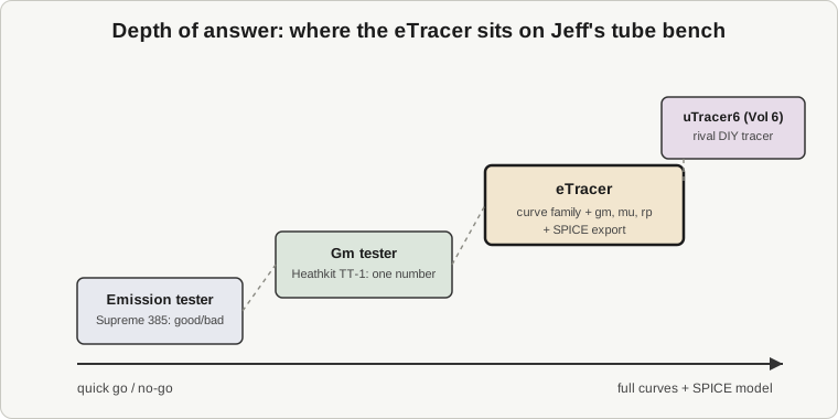
That is why it sits at the deep end of the bench, paired with the emission and Gm testers rather than replacing them. You reach for the 385 or the TT-1 when you want an answer in ten seconds; you reach for the eTracer when you want the truth about the tube.
1.6 The rival on the same bench: the uTracer6
The eTracer does not sit alone at the deep end. Its direct rival, Dekker’s uTracer6, is on the same bench, and the two are worth keeping straight because they arrived at the same core idea independently and then diverged.
Both use the charge-a-capacitor-then-pulse trick. But the uTracer6 is a Dutch DIY kit you assemble and solder yourself, reaching a higher, kilovolt-class envelope (the exact Vp/Ip figures are handled in Vol 6), driven by a different host stack. The eTracer is a Taiwanese commercial assembled board with a 0-750 V / 300 mA envelope per rail, a higher-resolution 14-bit ADC, and a Python host. The full head-to-head — spec table, workflow differences, price — lives in Vol 6, and I will not pre-empt it here. What matters at the overview level is that these are two different products by two different designers from two different countries that independently converged on pulsed-HV curve tracing, and having both on the bench is deliberate: it is a chance to see where each design made a different trade.
1.7 Getting the provenance right (because it is easy to get wrong)
This is the one place I want to be unambiguous, because the record is easy to muddle and I have seen it muddled.
The eTracer is Chris Chang’s / Essues Co., Ltd.’s design, out of Taiwan, introduced in late 2017. It is not Ronald Dekker’s work. Dekker is a Dutch engineer who designed the entirely separate uTracer / uTracer line, hosted at dos4ever.com — a different person, a different country, a different product family.
The relationship between the two, in Essues’s own telling, is this: the eTracer project began with the goal of building an enhanced version of the uTracer, but it evolved into a completely new design that “shares very little with the uTracer except the concept of using a charged capacitor to provide the high voltages required during measurement pulses.” Chang has said he offered Dekker a collaboration to improve the uTracer, the proposal was declined, and he decided to start from scratch. In the uTracer community the framing is blunt: the eTracer is “the competition.”
So the causality runs one way and one way only. The uTracer line predates the eTracer and inspired it. The eTracer did not spawn the uTracer, is not an ancestor of the uTracer3 or uTracer6, and is not a variant within that family. It borrowed a concept from a rival and built its own machine. Every time this dive refers back to that lineage — and Vol 2 traces it in full — that is the direction to hold in mind.
1.8 The safety frame, stated once and meant
One thing the “paperback-sized box” framing must never soften: this instrument makes and stores lethal high voltage. The HV rails reach up to 750 V, and the whole point of the architecture is that a reservoir capacitor sits charged to that voltage between pulses. Stored capacitor energy at 750 V does not care that the pulse is over. Anything you touch inside this instrument, or on a tube socket wired to it, is to be treated as live until proven discharged. Discharge discipline and interlock discipline are mandatory, not optional. Vol 5 gives this the full treatment it deserves; it is raised here so that nothing else in this overview reads as an invitation to be casual.
1.9 How the rest of the dive is laid out
This volume is the orientation. The specifics live in the volumes that follow:
- Vol 2 — Origin and the pulsed-HV tube-tracer landscape: how curve tracing works against vintage Tek iron and against emission/Gm testers, the uTracer as prior art, Chang’s “declined collaboration, started from scratch” story in full, and exactly how the eTracer differs from and rivals the uTracer.
- Vol 3 — Hardware architecture and how it measures: the dual reservoir-cap HV rails, the SMPS charging scheme, the pulse and sampling chain, the filament and grid supplies, and the protection.
- Vol 4 — Operating it: the Python host software, Full Scan vs Corners, measuring triodes, twin-triodes, and pentodes, reading the curve family, extracting gm/mu/rp, exporting data and SPICE models, and the software’s limitations.
- Vol 5 — Setup, calibration, and upkeep: the chassis build, sourcing good sockets and HT wire, the PSU polarity caution, calibration, maintenance, and the full safety discipline.
- Vol 6 — Cheatsheet plus the head-to-head with the uTracer6: quick-reference specs and workflow, then the full comparison table and prose.
With the orientation set — commercial assembled pulsed-HV tube curve tracer, Essues/Chang, Taiwan, 2017, inspired-by-not-descended-from the uTracer — the rest of the dive can go deep without having to keep re-establishing what the thing actually is.