eTracer · Volume 2
eTracer — Vol 2: Origin & the Pulsed-HV Landscape
Chris Chang started from scratch — the uTracer as prior art, and how the eTracer rivals it
2.1 Where the eTracer sits
Vol 1 established what the box on the bench is: a PC-controlled, pulsed-HV vacuum-tube curve tracer, a fully assembled commercial product from Chris Chang / Essues Co., Ltd. of Taiwan, introduced late 2017. This volume answers the two questions that actually matter for placing it in the history of tube test gear: what problem does pulsed-HV curve tracing solve that older instruments do not, and where did the eTracer come from — because the provenance is widely stated backwards, and the correction is worth getting on the record before any of the hardware volumes.
Two claims are commonly repeated and both are false:
- The eTracer is not Ronald Dekker’s design.
- The eTracer did not “evolve into” the uTracer3/6 line — the causation is backwards.
Both are corrected in detail below. The short version: the uTracer line predates and inspired the eTracer; the eTracer is an independent Taiwanese competitor that borrowed exactly one idea — charging a capacitor and pulsing the tube — and shares “very little” else.
2.2 What a tube curve tracer is doing
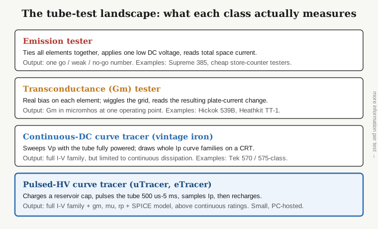
A tube curve tracer plots families of plate-current curves and reports the parameters an engineer actually designs with: quiescent current, transconductance (gm), amplification factor (mu), and plate resistance (rp). To see why that is a different animal from the rest of the tube-test bench, it helps to line the instrument classes up by how much they tell you per test.
2.2.1 Emission and transconductance testers — the lower rungs
Vol 1’s “Why it earns bench space” walks the bottom two rungs in detail with the same Supreme 385 (emission) and Heathkit TT-1 (transconductance) examples, so I will not re-run them here. The one-line version: an emission tester gives a single go/weak/replace number, and a dynamic mutual-conductance tester gives gm at a single operating point as a meter reading — neither shows the shape of the curve. The two rungs that follow are Vol 2’s contribution, because both draw the whole I-V family and it is the difference between them that places the eTracer.
2.2.2 Continuous-DC curve tracers — the whole family, at a cost
To see the shape — the full I-V family — you sweep the plate voltage while the tube is fully powered and draw the resulting curves on a CRT. That is what the classic bench iron does (the Tektronix 570 and 575-class instruments are the archetype). It is the real thing: full plate-current families, read directly. The price is physical. Because the tube is dissipating continuously through the sweep, the instrument needs a big, expensive continuous HV supply, and you are limited to the tube’s continuous dissipation rating — push a curve into the region where the tube would run hot in service and you cook it on the bench.
2.2.3 Pulsed-HV curve tracers — the family without the furnace
The top rung, and the eTracer’s home. Instead of a continuous HV supply, a switched-mode supply charges a reservoir capacitor to the target voltage, then switches that capacitor onto the tube for a brief pulse — 500 us to 5 ms in the eTracer — while a fast ADC samples the plate current during the pulse. Then the HV is switched off and the capacitor recharges for the next bias point. Chang draws the same analogy Dekker does: it is a camera flash. A small supply trickles energy into a reservoir, and that energy is dumped in a controlled burst.
The payoff is twofold. First, because the tube only sees full plate voltage for a few milliseconds at a time and idles between points, you can characterize it above its continuous dissipation rating without damage — the average power stays low even though the instantaneous operating point is stressful. Second, the whole HV section shrinks to something that fits on a ~21 cm x 15 cm PCB and runs off a 29 VDC / 3 A input, because it never has to source the full pulse current continuously. You get the Tek-570 deliverable — full curve families, gm/mu/rp, and in the eTracer’s case a SPICE model — out of a small PC-hosted box. That combination is why pulsed-HV tracers are the defining modern tool for characterizing NOS and pulled tubes, and why two of them (this and the uTracer6) share Jeff’s bench.
2.3 The uTracer as prior art
The pulsed-HV, PC-hosted approach did not start in Taiwan. It is Ronald Dekker’s, developed on dos4ever.com over the uTracer line. Dekker is a Dutch engineer (TU Eindhoven, Philips Research, PhD from TU Delft in 2004) — a different person, a different country, and a different product family from the eTracer.
The uTracer line is a series of DIY kits:
- uTracer3 — the popular kit version, the one that put the concept in a lot of hands.
- uTracer3+ — the higher-spec successor, which replaced the uTracer3 starting in January 2015.
- uTracer6 — the kilovolt-class model, around 2019; the direct rival to the eTracer on Jeff’s bench and the subject of its own dive here.
- uTracerNXT — a completely new design (not a warmed-over 3+), specified at 0–500 V / 350 mA with grid down to about −120 V and a 10-bit ADC.
(Exact per-plate Vp·Ip figures for the individual uTracer 3 / 3+ / 6 models are widely quoted but were not pinned to a primary dos4ever spec page in this research pass, so I am not going to assert specific numbers for them here; the head-to-head that does have firm figures — eTracer vs uTracer6 — lands in Vol 6.)
The essential point for this volume is chronology: every one of those milestones except the uTracer6/NXT predates the eTracer’s late-2017 introduction. The uTracer was mature, kit-proven, and well documented before Chang shipped a single eTracer. It is prior art in the plain sense — the charged-capacitor pulse method for PC-hosted tube curve tracing was Dekker’s established approach, and the eTracer is a later entrant into a category Dekker had already defined.
2.4 “Started from scratch” — the origin story, corrected
Here is what actually happened, in Essues’s and Chang’s own words.
Chang set out to build a better uTracer. Essues states it directly: “the original goal of the etracer project was to create an enhanced version of the uTracer.” Toward that end, Chang approached Dekker with a collaboration proposal to improve the uTracer. It was declined — in Chang’s telling, “Ronald didn’t like my proposal and hence I decided to start from scratch.” What began as an enhancement effort therefore became a clean-sheet design: the project “eventually evolved into a completely new design that shares very little with the uTracer except the concept of using a charged capacitor to provide the high voltages required during measurement pulses.”
That single sentence is the whole relationship. Shared: the charged-capacitor pulse concept. Not shared: essentially everything else — the circuit design, the HV envelope, the converters, the host software, the physical form, and the commercial model. This is not a fork of the uTracer codebase or PCB; it is an independent implementation of the same idea, by a competitor, arrived at after a rejected collaboration.
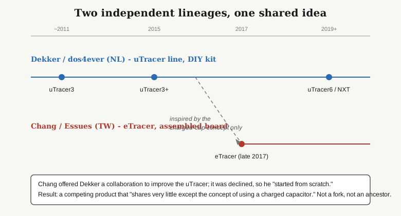
The uTracer community frames the two exactly this way. In the utracer Google Group the eTracer is discussed plainly as competition — “Ron is the competition” — not as a relative, a predecessor, or a variant. There is no lineage between them beyond the shared physics of pulsing a reservoir capacitor into a tube.
2.5 How the eTracer differs from — and rivals — the uTracer
If the two share only the pulse concept, the interesting question is where they diverge. The differences fall into four buckets. Full specifications and the numeric head-to-head table live in the hardware volumes (Vol 3) and the comparison volume (Vol 6); what follows is the shape of the rivalry, kept to facts I can stand behind.
2.5.1 Commercial assembled product vs DIY kit
This is the biggest practical split and the one a buyer feels first. The uTracer ships as an unassembled kit — you solder it. The eTracer ships as a fully assembled, tested, and calibrated SMD PCB. You do not solder the board; you integrate the finished board into a chassis and wire up the tube sockets, connectors, and HT wiring yourself.
That difference cascades into cost and audience. The eTracer is a commercial product with commercial pricing (roughly $600 for hardware-plus-software in early 2018, drifting to roughly $830–$1,080 for a full kit — board, PSU, chassis, Windows software license — in later configurations; treat all figures as approximate and dated). It targets someone who wants the pulsed-HV capability without building the analog front end. The uTracer targets someone who wants the kit-building experience and the lower entry price that comes with doing the assembly labor yourself.
2.5.2 A higher measurement envelope, for its day
The eTracer’s edge over the uTracer of its introduction era was reach and resolution:
- HV rails: two independent supplies, each 0–750 V @ 300 mA, feeding plate (HV1) and screen or second plate (HV2). Chang notes he ran “intensive studies” pushing the topology past 1 kV before settling on 750 V — a deliberate engineering ceiling, not an accident. (Up to ~600 mA is quoted as reachable with a hardware modification, but the exact conditions are not documented, so I treat that as uncertain.)
- ADC: 14-bit at 900 k samples/s for current and voltage measurement — against the uTracer’s 10-bit converter. Four extra bits of resolution and a fast sample rate is a meaningful measurement advantage when you are trying to resolve small plate currents cleanly during a short pulse.
Note the hedge built into “for its day.” By the time of the uTracer6 (kilovolt-class, ~2019) the envelope comparison changes — the uTracer6 reaches higher voltage than the eTracer (its current figure is not firmly pinned here; the numeric head-to-head lands in Vol 6). The clean statement is that the eTracer out-specced the mainstream uTracer of late 2017 on voltage headroom and on ADC resolution, and that the direct eTracer-vs-uTracer6 contest (a genuinely close, trade-offs-both-ways match) is what Vol 6 tabulates.
2.5.3 The grid limitation
One place the eTracer does not win: it provides no positive grid drive. The grid supply runs from 0 to roughly −160 to −180 V (sources vary slightly; treat it as about −160 to −180 V), and that is negative-only. A positive-grid (“A2”) test mode exists in the software but is reported to be unreliable. For most small-signal audio triodes and pentodes negative-grid is all you need, but it is a real limit for characterizing tubes into positive-grid / grid-current regions, and it is a differentiator to keep in mind against uTracer models that offer a positive-grid extension.
2.5.4 A different software stack
The host software is written in Python (NumPy / SciPy / Matplotlib) and packaged as a Windows application — Bartola ran it on Linux under Wine. It produces curve/data exports to text, CSV, and PDF, curve images as JPEG/BMP, and — the feature that matters most for the modeler — SPICE model export, via Chang’s conversion utility, compatible with Derk Reefman’s ExtractModel workflow. That is a different toolchain and a different feel from the uTracer’s host software, and the full operating story (Full Scan vs Corners modes, twin-triode “one shot,” the software’s rough edges) is Vol 4.
2.6 Reading the rivalry straight
Stripped of the provenance errors, the honest summary of the eTracer’s origin is short. Ronald Dekker’s uTracer defined PC-hosted pulsed-HV tube curve tracing and proved it as a DIY kit through the first half of the 2010s. Chris Chang, at Essues in Taiwan, wanted a better one, proposed working with Dekker, was turned down, and built an independent competitor from scratch — keeping only the charged-capacitor flash-camera idea. He shipped it in late 2017 as a finished, calibrated, commercial product with a higher voltage envelope and a much better ADC than the uTracer of that moment, at a commercial price, with a Python host and SPICE export, and with one notable gap: no positive grid.
That is the frame the rest of this dive is built on. Vol 3 opens the box and walks the reservoir-cap HV architecture and the measurement chain in detail; Vol 6 puts the eTracer and the uTracer6 side by side with real numbers. Everywhere in between, the eTracer is treated as what it is: the Taiwanese commercial rival to Dekker’s line, not a member of it.