eTracer · Volume 5
eTracer — Vol 5: Setup, Calibration & Upkeep
Boxing the assembled board, the polarity trap, and living with 750 V
5.1 Where this volume sits
Vol 3 covered the hardware architecture — the reservoir-cap-based dual HV rails, the SMPS that charges a capacitor and switches it onto the tube, the 14-bit / 900 kSPS ADC that samples plate current during the pulse. Vol 4 covered driving the Python host: Full Scan, Corners, reading the curve family, exporting SPICE models. This volume is the bench-integration story that sits between them: what actually lands on the bench when you buy an eTracer, what you have to build and wire around it, the one wiring mistake that can destroy the board, what “calibrated” does and does not mean here, and the safety discipline that a 0-750 V pulsed-HV instrument demands.
The framing fact for everything below: the eTracer is a commercial, fully assembled product from Chris Chang / Essues Co., Ltd. (Taiwan), introduced late 2017. It is an independent design inspired by Dekker’s uTracer concept but is not a uTracer variant and not a Dekker design — the two “share very little except the concept of using a charged capacitor.” That matters here because, unlike the uTracer (which arrives as an unassembled solder kit), the eTracer arrives as a finished, tested, calibrated SMD board. The soldering iron is not the tool this volume is about. The chassis, the harness, and the safety plan are.
5.2 What arrives, and what does not
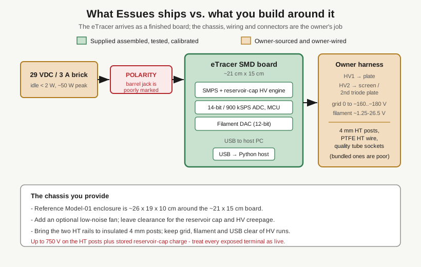
The eTracer ships as a fully assembled, tested and calibrated surface-mount PCB, roughly 21 cm x 15 cm. It is not a solder-it-yourself kit and not a publish-the-files DIY project — there is no BOM to stuff, no board to reflow. What you get is a working measurement engine with a USB connection to the host PC.
What you do not get is a usable instrument out of the box. The board has to be:
- Mounted in an enclosure. The reference Model-01 chassis is about 26 cm x 19 cm x 10 cm — enough to clear the ~21 x 15 cm board plus the reservoir capacitor, the connectors, and airflow.
- Fed from a 29 VDC / 3 A external supply (a separate brick, sourced by the owner).
- Wired to tube sockets and front-panel HV/grid/filament terminals with wiring the owner supplies.
So the buyer’s build is a packaging and wiring exercise, not an electronics-assembly one. That is a different skill set — mechanical layout, connector quality, HT insulation, cooling, and safety — and it is where most of the real bench work on this instrument lives.
5.2.1 The parts you have to source yourself
The reviewer who built one (Bartola Valves, Jan 2018) had to buy several things separately, and one of them is a quality complaint worth heeding:
- Tube sockets. The bundled Chinese sockets were called out as low quality. For an instrument whose entire value is repeatable contact resistance and clean curves, cheap sockets are a false economy — source good ceramic sockets for the base types you test most.
- 4 mm stackable plugs / posts for bringing the HV rails out to the panel.
- HT PTFE wire for the high-voltage runs. PTFE for the voltage rating and the temperature margin; this is the wire that carries up to 750 V.
- Extra ferrite beads for noise suppression.
- An optional low-noise fan for cooling.
None of these is exotic, but all of them are the owner’s responsibility, and the choices you make here — socket quality, HT wire routing, insulation clearances — set the ceiling on how clean and how safe the finished instrument is.
5.3 Boxing the board
The mechanical build is straightforward in principle and fussy in the details that matter for a pulsed-HV instrument.
5.3.1 Enclosure and layout
Size the box around the ~21 x 15 cm board with room for the reservoir capacitor and for the HT wiring to keep sensible creepage/clearance distance from low-voltage and signal runs. The Model-01 reference enclosure at ~26 x 19 x 10 cm is the sanity check on how tight you can go. Keep the three domains — the HT rails, the low-voltage/grid/filament wiring, and the USB/host connection — physically separated. The HV runs are the ones that bite; route them short, direct, and away from anything a hand reaches for during a socket change.
5.3.2 Bringing the rails to the panel
The instrument exposes, at the tube socket, four things the owner has to wire:
- HV1 -> plate (0-750 V @ 300 mA).
- HV2 -> screen on a tetrode/pentode, or the second plate of a twin-triode when you measure both halves “in one shot” (see Vol 4).
- Grid bias, 0 to about -160 to -180 V. There is no positive grid drive — a software “A2” positive-grid mode exists but is reported unreliable, so treat the grid supply as negative-only for planning the harness.
- Filament / heater, regulated DC roughly 1.25-26.5 V @ 3 A, up to 30 W (12-bit DAC control on the board side).
Bring the two HT rails out on insulated 4 mm posts — nothing bare that a probe tip or a finger can brush while the cap is charged. That is not a style preference on a 750 V instrument; it is the difference between a clumsy moment and a hospital trip.
5.3.3 Cooling
The board is efficient at idle (< 2 W) and the filament supply is quoted at >=85% efficiency, but capacitor charging draws up to ~50 W in bursts, and the filament path alone can dissipate a fraction of 30 W into the box. The optional low-noise fan earns its place if you run long scans or test big heaters. “Low-noise” matters twice: acoustically, and because a noisy fan motor near a 14-bit front end is a measurement-noise source — add the ferrite beads and keep the fan leads away from the ADC’s analog runs.
5.4 The polarity trap
This is the single most important paragraph in the volume for anyone assembling a unit.
The eTracer runs from 29 VDC / 3 A on an external barrel/DC input, and the power-supply polarity is poorly marked on the PCB. The reviewer’s words: “you can make a real mess if you get it wrong.” Reverse-feeding 29 V into an assembled, tested board is exactly the kind of mistake that turns a working instrument into a repair job before it has traced a single tube.
Concrete discipline before first power-up:
- Do not trust the silkscreen. Confirm the input polarity against the manufacturer’s documentation, not the board marking, and if there is any ambiguity, ask/verify before applying power.
- Meter the brick first. Set the DC supply/brick aside and confirm center-pin polarity and 29 V with a DMM at the connector before it ever touches the board.
- Match the connector convention explicitly. Note in your own build log which pin is positive on both the brick and the board; do not rely on “it’s usually center-positive.”
- First power-up with nothing in the socket. No tube, host software watching, hand near the disconnect.
The documentation being thin (below) makes this worse, not better — there is no lavishly illustrated build guide to catch you. Getting the polarity right is on the builder.
5.5 What “calibrated” means here
Essues ships the board tested and calibrated. The measurement chain that calibration backs is the 14-bit / 900 kSPS ADC on the current/voltage side and the 12-bit DAC on the filament-control side (Vol 3). In practice that means the unit should read plate current and voltage correctly out of the box without a user alignment step, which is a genuine advantage of buying an assembled commercial unit over building a kit and calibrating it yourself.
Two honest caveats:
- No detailed field-calibration procedure is published in the sources on hand. The unit is factory-calibrated; a documented user re-cal / verification routine of the kind you would expect from a bench DMM’s service manual is not something these sources establish. If you want traceable confidence, the pragmatic move is verification, not calibration — measure a couple of known references (a precision resistor as a known-current load, a tube with well-characterized published curves) and confirm the eTracer agrees, rather than adjusting anything. Treat any re-calibration as an unknown until Essues documentation for it is in hand.
- Documentation is thin generally. The build guide was noted as lacking assembly photos and practical guidance, and the community described the docs as incomplete relative to the uTracer’s standards as of early 2018. Budget time to work things out from first principles and to record what you learn in your own build log — that log is the calibration/verification record this instrument otherwise lacks.
5.6 The heater-compensation quirk
One measurement quirk belongs in the setup notes because it changes how you interpret results, not just how you wire the box.
At review time the host software had no heater-voltage compensation for large heater currents. The filament supply is regulated and DAC-controlled, but the wiring and connector resistance between the board and a high-current heater drops some voltage, and the software did not correct the setpoint for it. The practical consequence: for a big-heater tube, the voltage at the pins can sit below the voltage you dialed in, which shifts the operating point and therefore the curves.
Mitigations that stay inside what’s known:
- Use short, adequately-sized filament wiring and good socket contacts so the drop is small to begin with — this is another reason the bundled low-quality sockets are worth replacing.
- Be aware of it when comparing tubes with very different heater draw; a difference in curves between a small-signal and a big-heater tube can be partly a filament-voltage artifact rather than a real device difference.
- If it matters, measure the actual heater voltage at the socket and adjust the setpoint by hand to compensate, since the software will not.
This is a “know it’s there” item, not a defect to fix — but reading curves without knowing about it can send you chasing a tube difference that is really a wiring drop.
5.7 Upkeep
There is little to maintain on an assembled SMD board, and that is the point of buying one. The upkeep that does exist is mostly at the interfaces the owner built:
- Sockets. Contact resistance is the enemy of repeatable curves. Keep sockets clean, replace worn or intermittent ones (especially if you started with the low-quality bundled parts), and treat a socket that gives inconsistent readings as the first suspect, not the board.
- HT wiring and connectors. Inspect the 4 mm posts and HT PTFE runs for insulation damage and for any loosening at terminations — an intermittent HV connection on a 750 V rail is both a measurement problem and a safety one.
- Cooling. Keep the fan and vents clear of dust; a stalled fan on a box that peaks at ~50 W during charging is a slow thermal problem.
- The brick. The 29 VDC supply is a consumable; a failing brick can sag under the ~50 W charging peaks. If charging behaves oddly, meter the supply under load before suspecting the board.
- The host side. The Python software (Windows, or under Wine on Linux) and its export chain are the other maintenance surface — keep the working host and the SPICE-export utility together and versioned, since the analysis capability lives there (Vol 4), not on the board.
5.8 Safety: living with 750 V
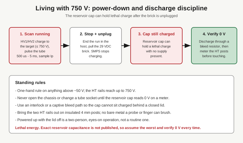
The eTracer generates up to 750 V on each of two HT rails, and it stores energy in a reservoir capacitor as part of its normal operation. That combination — high voltage plus stored charge — is lethal, and it stays dangerous after the instrument is switched off and unplugged, because the cap can hold its charge with no supply present.
The standing rules on this bench for this instrument:
- One-hand rule on anything above ~50 V. The HT rails reach 750 V; keep the other hand in your pocket.
- Bleed and verify before reaching in. Do not open the chassis or change a socket until the reservoir capacitor has been discharged through a bleed resistor and metered to 0 V at the HT posts. “The scan is stopped” and “the brick is unplugged” are not the same as “the cap is discharged.”
- Interlock discipline. Arrange the build so the reservoir cap cannot sit charged behind a closed lid — a captive bleed path or an interlock is worth the effort on an instrument that normally leaves a charged capacitor at the end of a run.
- No bare HV metal. The insulated 4 mm posts from the build section are a safety control, not just tidy panel work — there should be nothing at HV potential that a probe or a finger can brush.
- Lid-off, powered-up is a special operation, done deliberately and ideally with a second person aware, not a casual “let me just check something” move.
One honest limit on quantifying the hazard: the exact reservoir capacitance is not published in the sources on hand, so the stored energy cannot be given as a number here. That does not soften the rule — it hardens it. Assume the worst-case stored charge, discharge deliberately, and verify 0 V every single time before any part of you goes near the HT side. The general bench-discipline notes in ../_shared/legal_ethics.md apply in full; this instrument is squarely in the “potentially lethal currents” category they describe.
5.9 Where this leaves the instrument
Boxed properly, an eTracer is a low-maintenance, factory-calibrated pulsed-HV tube tracer whose day-to-day upkeep is mostly keeping sockets and HT connections honest and treating the 750 V with the respect it demands. The build risk is front-loaded: get the polarity right, buy good sockets, insulate the HV, and plan the discharge path, and the rest is running the host software (Vol 4) and reading curves. Vol 6 turns to the quick-reference cheatsheet and the head-to-head against the rival uTracer6 — where the assembled-vs-kit split described here becomes the central point of the comparison.