eTracer · Volume 6
eTracer — Vol 6: Cheatsheet + eTracer vs uTracer6
Quick reference, and the two rival tube tracers on one bench, head to head
6.1 What this volume is
Five volumes in, the eTracer has been dismantled to the level a bench technician needs: what it is and where it came from (Vol 1), the pulsed-HV tube-tracer landscape it competes in (Vol 2), the reservoir-cap hardware and how it samples plate current (Vol 3), the Python host software and the day-to-day operating procedure (Vol 4), and the chassis integration, calibration, and safety discipline (Vol 5).
This closing volume does two jobs. First, a quick-reference cheatsheet — the numbers, ranges, and the operating sequence condensed to what fits on a card taped inside the chassis lid. Second, the head-to-head with the uTracer6 — the other pulsed-HV tube curve tracer on the bench, Ronald Dekker’s kilovolt-class DIY kit, and the natural point of comparison every time a tube goes into a socket and the question is which tracer do I reach for.
One thing to keep straight from the start, because it is the single most-repeated error about this instrument: the eTracer is Chris Chang’s / Essues Co., Ltd. design (Taiwan, introduced late 2017). It is an independent commercial competitor to Dekker’s uTracer, inspired by the uTracer’s charged-capacitor concept but not a member of that product line. It is not a Dekker design, not a uTracer variant, and not an ancestor of the uTracer3/6 — the causation runs the other way, the uTracer line predates and inspired the eTracer. In Essues’s own words the two “share very little with the uTracer except the concept of using a charged capacitor to provide the high voltages required during measurement pulses.” Keep that framing through the whole comparison below.
6.2 The cheatsheet
6.2.1 Identity
Table 1 — Identity
| Field | Value |
|---|---|
| Instrument | eTracer — PC-controlled pulsed-HV vacuum-tube curve tracer / tube tester |
| Maker | Chris Chang, Essues Co., Ltd. (Taiwan) |
| Introduced | Late 2017 (>500 units sold per the maker’s claim) |
| Class | Commercial, fully assembled/tested/calibrated SMD board (not a solder kit) |
| Canonical source | essues.com/etracer |
| On this bench | Paired against the rival uTracer6 (Dekker DIY kit) |
6.2.2 Electrical envelope
Table 2 — Electrical envelope
| Parameter | Value |
|---|---|
| HV1 / HV2 (plate & screen rails) | 0-750 V @ 300 mA each, two independent rails |
| HV1 role | plate |
| HV2 role | screen (tetrode/pentode) or 2nd plate of a twin-triode |
| Grid (negative) supply | 0 to approx. -160 to -180 V |
| Positive grid | none (an “A2” mode exists in software but is reported unreliable) |
| Filament / heater | regulated DC approx. 1.25-26.5 V @ 3 A, up to 30 W; >=85% efficient; <2 W idle |
| Measurement pulse | 500 us to 5 ms (micro-controller timed) — not microseconds |
| ADC | 14-bit, 900 kSPS (current & voltage) |
| DAC | 12-bit (filament-voltage control) |
| Input power | 29 VDC / 3 A; approx. 50 W peak extra during cap charging; <2 W idle |
| Protection | over-current / over-voltage / short-circuit |
| PCB size | approx. 21 cm x 15 cm (Model-01 chassis approx. 26 x 19 x 10 cm) |
Note: up to approx. 600 mA per rail is quoted as achievable with a hardware modification, but the exact conditions are not documented — treat as a maker claim, not a rated figure.
6.2.3 Measurement method in one paragraph
An SMPS charges a reservoir capacitor to the target plate voltage. That charge is then switch-connected onto the tube’s plate for a brief pulse (500 us-5 ms). Plate current is sampled during the pulse by the 14-bit / 900 kSPS ADC, the HV is switched off, and the reservoir cap recharges for the next bias point. This is the “flash-camera” trick — store energy slowly, dump it briefly — which lets the instrument characterize a tube well above its continuous dissipation rating without cooking it. Call the architecture a pulsed capacitor-discharge / reservoir-cap HV design; “switched-capacitor” (as in SC filters) is the wrong term of art. Full detail is in Vol 3.
6.2.4 Software & output
Table 3 — Software & output
| Item | Value |
|---|---|
| Host language | Python (NumPy / SciPy / Matplotlib) |
| Platform | Windows application; runs under Wine on Linux (Bartola’s route) |
| Test modes | Full Scan (Ip family vs stepped Vp at stepped grid bias); Corners (checks extremes) |
| Reported parameters | quiescent current Iq, transconductance gm, amplification factor mu, plate resistance rp |
| Data export | text, CSV, PDF; curve images as JPEG/BMP |
| SPICE export | yes — via Chang’s conversion utility, compatible with Derk Reefman’s ExtractModel workflow |
| Twin-triode | measured “in one shot” using both HV rails |
6.2.5 Operating sequence
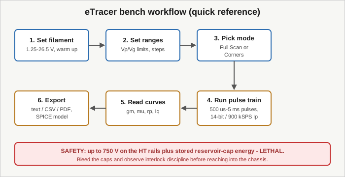
- Set the filament/heater voltage for the tube under test and let it warm up (12-bit DAC control, ~1.25-26.5 V).
- Set the plate/screen voltage limits and grid-bias steps; choose the sweep resolution.
- Pick the test mode — Full Scan for the full curve family, Corners for a fast extremes check.
- Run. The board charges, pulses (500 us-5 ms), and samples Ip on the 14-bit ADC for each bias point.
- Read the curve family; the host extracts gm, mu, rp, and Iq. (No grid-current measurement — see limits.)
- Export to text/CSV/PDF or emit a SPICE model for simulation.
6.2.6 Known limits (carry these in your head)
- No positive-grid drive. The A2 mode exists but is unreliable — do not trust it for real class-A2/AB2 characterization.
- No grid-current measurement at all.
- Thin documentation — the build guide lacks assembly photos and practical guidance.
- PSU polarity is poorly marked on the PCB — get it wrong and “you can make a real mess.” Verify polarity against a meter before first power-up.
- Basic host graphics — can’t zoom without losing plots, no drag-cursor readout, pentode-mode settings not validated by the software.
- Heater compensation — no heater-voltage compensation for large heater currents (at review time).
- Bundled tube sockets were low quality — plan to re-source good sockets, 4 mm stackable plugs, and PTFE HT wire (Vol 5).
6.2.7 Safety (non-negotiable)
Up to 750 V sits on the HT rails, and the reservoir capacitor stores real energy even after the SMPS is off. This is lethal. Bleed the caps and honor interlock/discharge discipline before reaching into the chassis. The one-hand rule applies to everything above ~50 V. Full treatment in Vol 5.
6.3 The other tracer on the bench: uTracer6
The eTracer does not sit on the bench alone. Next to it is the uTracer6 — Ronald Dekker’s high-voltage model in the uTracer line (dos4ever.com), a DIY kit the owner solders and builds rather than buying assembled. The two instruments arrived at the same core idea independently: charge a capacitor, pulse the tube, sample the current, and thereby characterize tubes above their continuous ratings with a small, cheap supply. Everything past that shared concept diverges.
A short history matters here because it is so often told backwards. The uTracer line predates the eTracer. Dekker’s miniature curve-tracer work runs back through the uTracer V2, the popular uTracer3 kit, the uTracer3+ (from January 2015), and the kilovolt-class uTracer6 (around 2019), with the clean-sheet uTracerNXT more recent still. Chris Chang, wanting an enhanced uTracer, says he offered Dekker a collaboration; Dekker declined the proposal, so Chang “started from scratch” and shipped the eTracer in late 2017 as an independent product. Within the uTracer community the eTracer is framed plainly as competition — “Ron is the competition.” So the honest one-line relationship is: the eTracer is a 2017 Taiwanese competitor inspired by the uTracer, not a branch of it.
One caution on the numbers that follow. The eTracer figures are pinned to Essues’s own spec pages and the Bartola build/review. The uTracer6 figures below are the widely-quoted spec for that model (0-1000 V / 1 A, 10-bit converter, optional positive-grid extension, Visual-Basic host, ~EUR 329 kit) and are used here as the standard point of comparison, but they are not independently confirmed here to the same degree as the eTracer figures — treat the uTracer6 column as “commonly quoted,” not verified.
6.3.1 Envelope, side by side
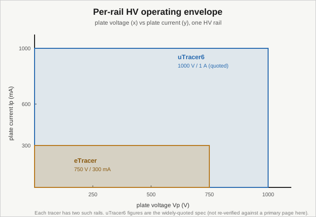
The envelope picture is the fastest way to see where each tracer wins. The eTracer’s per-rail box is 750 V by 300 mA. The uTracer6’s commonly-quoted box is larger in both axes — 1000 V by 1 A — which is exactly what you want when the tube under test is a sweep tube, a beam-power output tube run hard, or a transmitting tube whose interesting operating points live past 750 V or past a few hundred milliamps. Below that boundary — receiving triodes, small-signal pentodes, preamp and phase-splitter tubes, most of what a hi-fi or guitar-amp bench sees — both instruments cover the ground, and the contest shifts to resolution, features, and workflow.
6.3.2 Comparison table
Table 4 — Comparison table
| Aspect | eTracer (Essues / Chang, Taiwan, 2017) | uTracer6 (Dekker, NL) |
|---|---|---|
| Product form | Commercial, fully assembled/tested/calibrated SMD board | DIY kit — buyer solders and builds |
| HV rails | Two rails, 0-750 V @ 300 mA each | Commonly quoted 0-1000 V / 1 A |
| Negative grid | 0 to approx. -160 to -180 V | (kilovolt-class negative bias; figure not verified here) |
| Positive grid | None (A2 mode unreliable) | Optional positive-grid extension (commonly quoted) |
| Reservoir/pulse method | Charge cap, switch onto tube, pulse 500 us-5 ms | Same charged-capacitor “flash” concept, independently designed |
| Plate-current sampling | 14-bit ADC, 900 kSPS | 10-bit converter (commonly quoted) |
| Filament control | ~1.25-26.5 V @ 3 A, 12-bit DAC, up to 30 W | (regulated heater supply; figure not verified here) |
| Host software | Python (NumPy/SciPy/Matplotlib), Windows; Wine on Linux | Visual Basic host (commonly quoted) |
| Data / model export | text/CSV/PDF, JPEG/BMP; SPICE via Reefman ExtractModel workflow | SPICE export part of the uTracer ecosystem (commonly quoted) |
| Price (approx., dated) | ~$600 (2018 HW+SW) up to ~$830-1,080 full kit later | ~EUR 329 kit (commonly quoted) |
| Documentation | Thin — build guide lacks assembly photos | Extensive, well-regarded (community’s own benchmark) |
| Lineage | Independent 2017 competitor, inspired by the uTracer | The line that predates and inspired the eTracer |
6.3.3 Reading the table — where each one wins
Resolution vs. reach. The two headline differences pull in opposite directions. The eTracer brings the finer front end: a 14-bit / 900 kSPS ADC against the uTracer6’s commonly-quoted 10-bit converter — more bits of current/voltage resolution per sample, which matters when you are chasing small differences between tubes for matching or trying to resolve low-current tail behavior. The uTracer6 brings the bigger envelope: a 1000 V / 1 A reach against the eTracer’s 750 V / 300 mA, which matters the moment a tube’s useful operating region exceeds what the eTracer can put across it. Neither wins outright; they optimize different corners of the same problem.
Positive grid. This is a real functional gap, not a nicety. The eTracer has no usable positive-grid drive (the A2 mode is present but unreliable) and no grid-current measurement, so class-A2/AB2 operation — where the grid is driven positive and draws current — cannot be characterized honestly on it. The uTracer6’s optional positive-grid extension (as commonly described) covers that case. If the bench work involves positive-grid output stages, that alone can decide which tracer comes out.
Assembled vs. kit. The eTracer arrives as a finished, calibrated board — you build a chassis and wire sockets, but you never touch a reflow profile or a fine-pitch QFP. The uTracer6 is a solder-it-yourself kit; you get the satisfaction, the lower price, and the debugging that comes with a DIY build. This is the DIY-vs-buy duality the whole TestEquipment hub runs on, expressed in one pair of instruments: pay more for a turnkey assembled unit, or pay less and build it.
Software. Python (eTracer) vs. Visual Basic (uTracer6, as commonly described). The eTracer’s Python base is nominally cross-platform — it runs under Wine on Linux, which is how Bartola drove it — but the vendor packages and licenses it for Windows, and the host graphics are basic (no lossless zoom, no cursor readout). The uTracer’s host software is the community’s own documentation benchmark; the eTracer’s thin docs are a repeated complaint. Both ecosystems land in the same place that matters for downstream work: SPICE model export, so a measured tube can become a simulation model.
Price. The eTracer is the more expensive instrument — roughly $600 for hardware-plus-software in 2018, climbing to roughly $830-1,080 for a full kit (motherboard + PSU + chassis + Windows license) in later configurations. The uTracer6 kit is commonly quoted around EUR 329. Prices on both drift with time and configuration; treat every figure as approximate and dated.
6.3.4 Which one do I reach for
The practical decision rule that falls out of the bench:
- Small-signal and receiving tubes, tube matching, fine current resolution, publishable curves, and you want a finished instrument you didn’t have to solder: the eTracer. The 14-bit front end and the assembled-and-calibrated board are the draw.
- Sweep tubes, beam-power output tubes run hard, transmitting tubes, anything living past 750 V or past a few hundred milliamps, or positive-grid (A2) characterization: the uTracer6. The kilovolt/amp envelope and the optional positive-grid extension are the draw.
- Both tubes are inside the eTracer’s box and you just want curves and a SPICE model: either works; reach for whichever is already wired and warmed up.
That is exactly why both sit on this bench rather than one replacing the other — they cover adjacent, overlapping corners of the same tube-characterization problem, and the overlap is wide enough that most everyday tubes can go into either socket.
6.3.5 Where the tube tracers sit in the wider bench
Neither pulsed-HV tracer replaces the go/no-go testers. On this bench the Heathkit TT-1 gives a fast dynamic-transconductance number and the Supreme 385 gives an emission reading — both are quick-triage instruments that answer “is this tube alive and roughly good” in seconds without a PC. The eTracer and uTracer6 answer the deeper question — the full plate-current family, gm/mu/rp extracted, and a SPICE model out the other end — at the cost of a host computer and a longer setup. The complete workflow is triage on the TT-1 or 385, then full characterization on a pulsed-HV tracer when a tube is worth curves. See the eTracer subproject cross-links to the uTracer6, the Heathkit TT-1, and the Supreme Instruments 385, plus the Curve Tracers Overview primer.
6.4 Closing note
The eTracer earns its place next to the uTracer6 not by being better but by being different in the right direction: a finer 14-bit front end and a finished, calibrated board, traded against a smaller envelope and no positive grid. Buy the framing right and everything else follows — it is Chris Chang’s independent 2017 Essues design, inspired by Dekker’s uTracer, competing with it, sharing only the charged-capacitor pulse concept. Get that straight and the two tracers stop being confusable and start being complementary tools, which is exactly how they earn their bench space.