Radio Shack 43-114 Telephone Tester · Volume 1
Radio Shack 43-114 — Vol 1: Overview — What the 43-114 Actually Is
A 1985 central-office simulator that grades a phone set PASS/FAIL — not a line tester
1.1 The one-sentence identity
The Radio Shack “Telephone Tester,” Cat. No. 43-114, is a benchtop console — roughly 13 pounds, powered from the 110–120 V / 60 Hz AC mains, and controlled by a Motorola MC6805P2 microprocessor — that simulates a central office and grades a telephone set (or a telephone answering device) as PASS / FAIL across a battery of functional tests. Tandy built it in the United States and copyrighted it in 1985. The manual cover calls it, plainly, “TELEPHONE TESTER,” and the front matter frames it as “a multifunction, value featured advance in telephone service technology.”
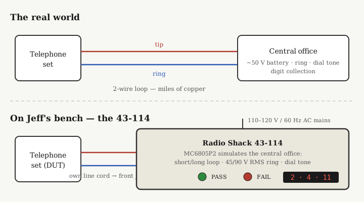
That phrase “telephone service technology” is the key. This box services telephones — the instrument on the desk, the handset, the answering machine — not the copper pair running out to the pole. It is a shop tool. You put a phone on the bench, plug the phone’s own line cord into a jack on the front panel, and the 43-114 pretends to be the phone company: it offers a simulated loop, throws ringing voltage at the ringer, generates a dial tone, collects the digits you dial, and lights a green PASS lamp or a red FAIL lamp for each function. There is no analog meter anywhere on it, and there is no numeric voltage or current readout of a live line — because there is no live line. The tester is the line side.
1.2 What it is NOT — clearing the biggest misconception
Because the words “telephone” and “tester” sit next to each other, and because Radio Shack sold cheap two-wire line checkers under nearby catalog numbers, the 43-114 is easy to misfile. So state the negatives explicitly, because every one of them is a thing this box does not do.
- It is not a POTS line tester. It does not clip onto a live subscriber pair out in the world and tell you what the phone company is doing on that pair.
- It is not a butt-set / test handset. You cannot monitor a call, seize dial tone from a real central office, or place an outbound call through it. It has no talk battery to an outside line and no way to dial out to a real CO.
- It is not a cable tester or a premises-wiring tester. It does not trace or map the in-wall extension wiring, jacks, or the outside plant.
- It is not a clip-on loop tester. There are no alligator clips and no inline pass-through. The phone plugs into dedicated modular jacks on the front panel; the tester supplies the simulated line conditions.
And within the numbers people expect from a line tester, the 43-114 supplies none of them as measurements:
- It does not display live-line tip/ring polarity. There is no polarity LED. The only tip/ring-adjacent function is the Cord Test, which checks a cord’s conductor count and integrity — and it tolerates a within-pair reversal and still passes the cord. It grades a cord, not a live line’s polarity.
- It does not read on-hook line voltage. It cites ~50 V DC on-hook only as background teaching (see below), and it generates ringing voltages as stimulus — but it never puts a measured line voltage on a display.
- It does not read loop current. Nowhere is there a milliamp readout. Its closest function, the Loop Test, grades off-hook DC resistance (57–600 Ω) as a PASS/FAIL — a resistance go/no-go, not a current measurement.
The practical takeaway: if a phone is dead and you want to know whether the phone is the problem or the line is the problem, the 43-114 answers only the first half. It tells you whether the phone is good. To interrogate the line itself you still reach for a real butt-set or line analyzer. That division of labor is the whole reason this tool existed — see §5.
1.3 The central-office-simulator idea
To understand what the 43-114 grades, hold the ordinary telephone loop in your head for a moment. In service, a telephone set connects to a central office (CO) over a pair of wires — tip and ring — that can run for miles. The CO maintains a DC “talk battery” on that pair; the manual’s own terminology page states it as a standard 50 V DC present at the phone with the handset on the hook (the real-world Bell nominal is 48 V; ~48–50 V on-hook is the right mental figure). When you lift the handset, the set closes the loop, DC flows, and how much flows depends on how far you are from the CO: close in — a short loop — the current might be as high as 0.08 A (80 mA); several miles out — a long loop — as little as 0.02 A (20 mA). To ring the phone, the CO superimposes an AC ringing voltage on the pair (nominally around 90 V RMS at ~20 Hz). To dial, the set either pulses the loop open and closed (rotary) or sends dual-tone pairs (Touch-Tone / DTMF), and the CO collects the digits. Vol 2 develops all of this loop physics in detail; here it matters only as the thing the tester imitates.
The 43-114 stands in for the CO across every one of those behaviors. It presents a loop the set can draw against. It can present that loop as Short Loop (near CO) or Long Loop (distant CO) so you can confirm the set works under both close and far electrical conditions. It drives the ringer, and it can do so at Low Ring (45 V RMS) for a distant-CO condition or High Ring (90 V RMS) for a nearby-CO condition. It generates a dial tone into the earpiece for the Receive test. It collects and displays the digits the set dials. In short, it manufactures the line-side stimulus and then judges how the phone responds.
That is why the framing “central-office simulator” is exact and “line tester” is wrong. A line tester passively observes a real CO’s line. The 43-114 actively is a synthetic CO, and the phone is the device under test.
1.4 How the phone connects — front-panel jacks, not clips
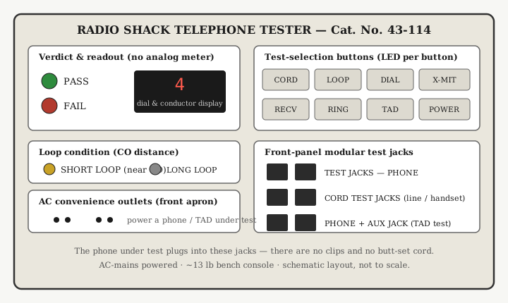
Everything meets the tester at the front panel, through modular RJ-type jacks grouped by labeled test area. There are no clips to attach and nothing to splice into.
The jack groups are:
- TEST JACKS — PHONE — the phone’s line-cord modular plug goes here for the Loop, Dial, Transmit, Receive, and Ring tests. This is the jack that carries the simulated line.
- CORD TEST JACKS — both ends of a line cord or a handset cord plug in here, end to end, for the Cord Test. This is a continuity/integrity check of the cord as a standalone part.
- PHONE TEST JACK + AUX TEST JACK — used together for the answering-machine (TAD) test: a known-good phone in the PHONE jack, the answering device in the AUX jack beneath it.
Two more panel features matter to the identity. First, the 43-114 is AC-mains powered only — the manual is explicit: “Insert the AC Line Cord into a source of 110–120 volts, 60 Hz” (supply spec 105–135 VAC). It is not battery powered and it is not self-powered from a phone line. That single fact rules out any field-butt-set reading of the tool: you need a wall outlet. Second, the front apron carries AC convenience outlets so that a phone or answering machine that itself needs household AC (a cordless base, a TAD) can be powered right there while under test.
Adapting non-standard sets is a matter of Radio Shack accessories rather than any change in method: a wall phone is reached through a Cat. No. 279-359 duplex adapter plus a 279-374 cord, and a two-line phone through a 279-401 two-line coupler. In every case the principle holds — the phone’s own cord plugs into the tester, and the tester supplies the line.
1.5 The readout — PASS/FAIL and a numeric LED, nothing to interpret on a meter
The 43-114’s verdict language is deliberately blunt, which is both its strength and its ceiling. There are four kinds of indication and no fifth:
- PASS lamp (green LED) and FAIL lamp (red LED) — the primary go/no-go verdict on most tests. Green means the phone did the right thing under the simulated condition; red means service it.
- Numeric LED display — labeled the “Dial and Conductor Display.” It shows the conductor count from the Cord Test (2 or 4), and it shows the digit dialed during the Dial Test, including 11 for
*and 12 for#on a Touch-Tone set. - Test-selection LEDs — an LED above each pressed test button lights to show which test is active, and the SHORT LOOP / LONG LOOP LED shows which loop condition is in effect.
- POWER lamp — lit when AC power is present.
There is exactly one audible cue in normal use, and it is not a verdict tone: during the Receive Test the tester generates a dial tone into the handset earpiece, and the operator listens for it. Hearing it means the receiver works; silence means a defective receiver. Every other result is a visual LED.
What is conspicuously absent is any metrology. No analog meter. No calibrated voltage, current, or resistance number for the operator to read and judge. The internal thresholds — the 57–600 Ω Loop Test window, the 45 V / 90 V RMS ring levels, the dial-pulse timing tolerances — live inside the firmware and never surface as a measured number. This is a go/no-go instrument by design. That is perfect for its intended user, who wants a fast, unambiguous verdict on a customer’s phone, and it is exactly why the 43-114 is not, and was never meant to be, a bench metering instrument.
1.6 Who used it, and why
The manual names its audience directly: “Office Equipment Sales/Service organizations” and “Telemarketing professionals,” and it states the payoff — to “avoid needless outside repairs” on customer-owned telephones. That sentence captures the entire business case. By the mid-1980s the U.S. telephone set had been deregulated; customers owned their own phones and answering machines, and a growing service trade existed to fix them. When a phone stopped working, the expensive move was to dispatch a technician to the outside line. The cheap move was to bench-test the phone first and settle the question — is the set bad? — before anyone touched the line. The 43-114 answered that question in a couple of minutes, with a green or red lamp, no telephony expertise required of the operator.
Concretely, the tester can handle single-line sets, Touch-Tone and rotary/pulse dialing, cordless phones, and answering machines, and it is “adaptable” to two-line phones with the coupler. The manual is equally clear about its ceiling: “This unit may not properly test Electronic Key Systems or PABX Key Sets.” Those multi-line business systems fall outside its simulated-single-line model. Vol 4 works through the full “can and cannot test” boundary; the headline is that it grades sets, not lines, and single-line and cordless sets are its sweet spot.
1.6.1 Why it is on Jeff’s bench
POTS is fading — most U.S. incumbents are retiring copper voice for VoIP and fiber — so the 43-114 is a reference instrument here, not a daily driver. It earns its shelf space three ways. First, a small but stubborn population of real POTS still exists — alarm-panel circuits, elevator phones, fax-only lines, rural service — and a working set tester still settles “is the phone the problem?” on those. Second, its cord and continuity functions generalize: a 2/4-conductor continuity-and-cross check is useful on intercoms, doorbells, and low-voltage signaling cordage well beyond telephones. Third, and most relevant to this deep dive, it is a compact, honest teaching artifact for how a 1980s central office actually behaved — talk battery, short/long loop, high/low ring, DTMF versus pulse — because it reproduces those conditions on demand and lets you watch a real phone respond to them.
One provenance caution worth recording now, since it circulates online: a frequently reposted photo of a 43-114 with an attached handset and carry handle is a custom-modified film prop, not a stock unit. The factory 43-114 is a plain bench console with front-panel jacks; treat the handset-and-handle version as a one-off, not a configuration.
1.7 Where this fits in the series
This volume fixes the identity: a 1985 Tandy AC-powered, MC6805P2-controlled bench console that simulates a central office and grades a phone set PASS/FAIL — decidedly not a line tester, butt-set, or cable tester. The rest of the dive builds outward from there. Vol 2 develops the POTS and telephone-set background the tester exercises — the two-wire loop, ~50 V talk battery, 20–80 mA loop current, ~90 V RMS ringing, DTMF versus pulse, and the handset transducers — as the phenomena the 43-114 simulates. Vol 3 opens the box: the MC6805P2 control, the front-panel jacks, and each of the ~7 functions in circuit detail. Vol 4 is operating procedure — running a set through the sequence and reading the verdicts, plus the can/cannot-test boundary. Vol 5 is the quick-reference cheatsheet, the tool’s place in the POTS heyday, and an honest comparison against a real butt-set or line analyzer.