Radio Shack 43-114 Telephone Tester · Volume 2
Radio Shack 43-114 — Vol 2: POTS & the Telephone Set
Tip/ring, talk battery, loop current, ringing, and dialing — the phenomena it simulates
2.1 Why this volume exists
The 43-114 is a central-office simulator. It does not clip onto a live subscriber pair, and it never reports a measured tip/ring voltage, polarity, or loop current. It manufactures the electrical world a telephone set expects to see — talk battery, loop closure, dial tone, ringing — and then grades the set PASS/FAIL against how it behaves in that world. To read the results of Vol 3’s cord/loop/dial/transmit/receive/ring/TAD sequence, or to understand why the Loop test grades resistance and not current, you have to know the plain-old-telephone-service (POTS) phenomena the box is imitating.
So this volume walks the subscriber loop and the telephone set as they existed in 1985: the two-wire tip/ring loop, the on-hook talk battery, off-hook loop current and its dependence on loop length, the hookswitch DC signature, ringing, pulse and DTMF dialing, and the handset’s transmitter and receiver. Each is framed as something the tester simulates or teaches — the manual’s own “Telephone Terminology” page is where these standard values come from — never as a live-line measurement the 43-114 performs.
One correction to keep in front of you throughout: every voltage and current below is a property of the network the phone plugs into. The 43-114 generates the network side; it grades the phone. It has no meter, no numeric voltage or current readout, and no line-polarity lamp. Its only numeric display is the digit/conductor count, and its only verdicts are PASS and FAIL lamps.
2.2 The subscriber loop: tip and ring
The manual’s terminology page states it plainly: your phone is connected to a central office by a pair of wires. That pair is the entire physical layer of POTS — two copper conductors, historically named tip and ring after the tip and ring contacts of the manual switchboard plug that once terminated them. Everything a single-line telephone does — talk battery, dialing, speech, ringing — happens differentially across those same two wires. There is no separate power, signaling, or audio conductor. That economy is the whole point of the design, and it is why the loop is called a two-wire circuit.
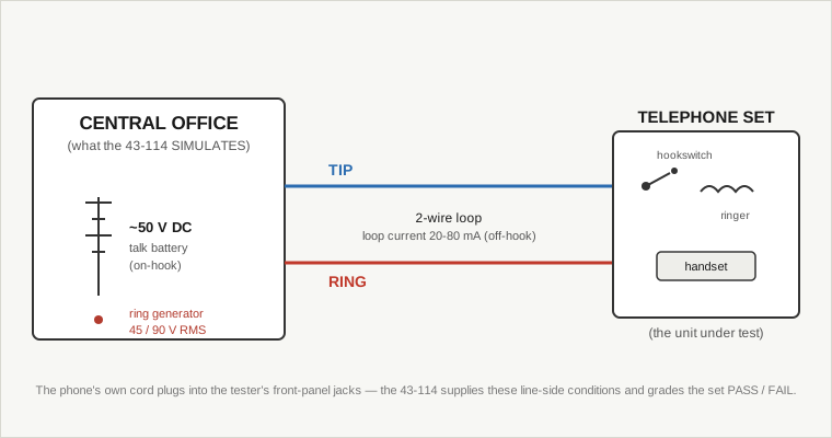
From the set’s point of view the loop is a DC source with a series resistance (the copper of the loop) that it can either leave open (on-hook) or close (off-hook), plus an AC ringing source the central office applies to alert it. From the central office’s point of view the set is a variable load: a near-open circuit when idle, a defined low resistance when off-hook, and a high-impedance bell/ringer bridged across the pair that responds to the ringing frequency. The 43-114 stands in for the central-office end of exactly this picture. The phone under test plugs its own line cord into the tester’s front-panel jacks, and the tester presents tip and ring with the conditions below.
Note what “tip and ring” does not mean here. The 43-114 has no live-line polarity indicator. The one place tip/ring pairing shows up in the test suite is the Cord test (Vol 3), which counts conductors in a cord — inner tip/ring pair plus outer pair — and tolerates a within-pair reversal while still passing. That is a continuity/integrity check on a cord plugged end-to-end into the tester, not a polarity reading on a working line.
2.3 Talk battery: the on-hook DC
The terminology page gives the standing condition: with the handset on the hook, there is “usually a standard voltage of 50 volts DC present in your phone.” This is the talk battery — a large central-office battery. The manual says 50 V; the real-world Bell nominal is 48 V; both figures are correct in common use. Treat the on-hook figure as ~48–50 V DC across tip and ring.
Two things about that battery matter for understanding the tester:
- It is a source, not a reading. The whole reason a central office (and therefore the 43-114) puts DC on the pair is to power the telephone and to sense, by current, whether the set has gone off-hook. The set has no local power for its speech circuit in a classic POTS phone — it draws everything it needs from this battery. The tester supplies the on-hook DC as part of simulating the loop; it does not display any on-hook voltage back to the operator, and there is no on-hook-voltage lamp or numeric field anywhere on the panel.
- On-hook is the high-impedance state. With the phone on-hook the DC loop is essentially open — the hookswitch has disconnected the set’s DC path, leaving only the ringer (AC-coupled, DC-blocked) bridged across the line. The manual’s Loop test leans on exactly this: on-hook it expects the set to return to an open, on the order of ~10 MΩ, and flags a set that fails to restore that open.
The DC talk battery is superimposed with the AC ringing described below; when the office rings a phone, the ~20 Hz ringing voltage rides on top of the DC.
2.4 Loop current, and why it tracks loop length
When the set goes off-hook it closes the loop, and DC flows: from the central-office battery, out one conductor, through the set, back on the other. This loop current is the signal the office uses to detect the off-hook condition and to power the transmitter. Its magnitude depends on how much series resistance the copper adds between office and set — that is, on how long the loop is.
The manual teaches the range directly. Close to the central office — a short loop — the current “might be as high as 0.08 ampere,” i.e. 80 mA. Several miles out — a long loop — “that current might be as small as 0.02 ampere,” i.e. 20 mA. So loop current runs roughly 20–80 mA, high on a short loop, low on a long one, because the far loop’s added copper resistance drops more of the fixed battery voltage before it ever reaches the set.
This is the physical basis for the tester’s Short Loop / Long Loop selection (Vol 3). Those two buttons switch the simulated loop between a near-CO condition and a far-CO condition so a set can be exercised under both. Long Loop is the power-up default; the speech and dial tests are repeated under Short Loop to confirm the set still works when the office is electrically close. An LED shows which loop condition is active.
Here is the guardrail the whole dive turns on: the 43-114 does not display loop current. The 20–80 mA figures are background — the phenomenon the Short/Long Loop simulation embodies and the reason the two settings exist. The related front-panel function is the Loop test, and it grades DC resistance, not current.
2.5 The hookswitch and the off-hook DC signature
Going off-hook is a mechanical event with an electrical consequence: the hookswitch closes the DC path through the set, and the pair’s resistance drops from open-circuit to the low value of the set’s DC loop. That low resistance is the set’s DC signature to the office. A healthy single-line set presents a well-defined, modest resistance off-hook; a set with a corroded hookswitch, a dried-out or shorted network, or a damaged cord presents the wrong resistance.
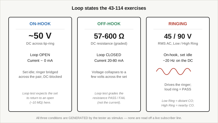
The Loop test is where the 43-114 grades this signature. It measures the off-hook DC resistance of the set’s switch-hook loop and passes it if it falls in the band 57–600 Ω, failing it outside that band. On-hook it expects the set to return to ~10 MΩ (an open) and flags a set that does not restore. The verdict is PASS/FAIL on the lamps — there is no resistance number shown to the operator; 57–600 Ω is an internal threshold, not a readout.
The two things people expect from a “loop tester” that this is not:
- It is not a loop-current meter. The related live-line quantity — the 20–80 mA the office would draw from a set — is background only. The tester grades resistance.
- It is not a live-line resistance meter either. It grades the resistance of a set plugged into the tester’s jacks, under the tester’s own simulated loop. It cannot be clipped across an outside pair to measure the plant.
The 57–600 Ω band and the 20–80 mA loop-current range are two views of the same physics — a set’s DC loop and the current a real battery would push through it — but the tester works in the resistance view because it is the network, sourcing the conditions, not a passive observer measuring current on someone else’s line.
2.6 Ringing
To alert an idle (on-hook) set, the central office superimposes a high-voltage, low-frequency AC ringing signal on the pair. Typical POTS ringing is on the order of 90 V RMS AC at about 20 Hz, riding on top of the DC talk battery. The set’s ringer — historically a coil-and-clapper bell, later an electronic ringer — is bridged across tip and ring through a capacitor that blocks the DC but passes the ringing AC, so it responds to ringing while staying invisible to the DC loop when idle.
The 43-114 generates ringing as stimulus and offers two levels, matching the near-CO/far-CO idea from loop current:
- High Ring — high-voltage ring, simulating a nearby central office. Spec: 90 V RMS.
- Low Ring — low-voltage ring, simulating a distant central office where line loss has attenuated the ringing voltage. Spec: 45 V RMS.
In the Ring test (Vol 3) the set is on-hook and the tester drives its ringer; a loud ring is a pass. The manual notes that some phones may legitimately fail to ring on Low Ring — a real set at the end of a long loop can be marginal on attenuated ringing — so a no-ring on Low Ring is not automatically a defect. The 45 V RMS and 90 V RMS figures are the values the tester produces; they are the closest thing in the manual to a “ring voltage,” and they are stimulus levels, not measurements read off a line. The TAD test for answering machines (Vol 3) uses High Ring to trip the machine before leaving it a test message.
A standing safety note for later volumes: 90 V RMS is a real voltage on the front-panel jacks during the Ring and TAD tests. It is generated by an AC-mains-powered console, not scavenged from a phone line, and it deserves the same respect as any other line-level source on the bench.
2.7 Dialing: pulse and DTMF
A telephone set has to tell the office which number to reach. Two methods coexisted in 1985, and the 43-114’s Dial test handles both, showing the dialed digit or character on the numeric LED display.
2.7.1 Rotary / pulse (loop-disconnect) dialing
The older method is pulse dialing: the rotary dial (or an electronic pulse dialer) rapidly opens and closes the DC loop, sending a train of current interruptions — one break per count, so “5” is five breaks. The office counts the pulses. Two parameters define a well-behaved pulse dialer, and the manual specs both as the pass window for the Dial test:
- Dial speed: 8–11 pulses per second (PPS), to a tolerance of ±0.1275.
- Make/break ratio: 58–64%, to a tolerance of ±0.6% — the fraction of each pulse cycle the loop is broken versus made.
A set outside those windows dials unreliably into a real office; the Dial test flags it. Because pulse dialing physically opens and closes the loop, it is inseparable from the loop-closure physics above — the same hookswitch-type make/break action, just modulated at 8–11 PPS.
2.7.2 DTMF (Touch-Tone)
The newer method is DTMF — dual-tone multi-frequency, the Touch-Tone system — where each key sends a pair of audio tones (one from a low group, one from a high group) simultaneously down the loop while it stays closed. The office decodes the tone pair into a digit. DTMF is faster and works over connections where pulse counting is unreliable.
For the Dial test the tester decodes the tones and shows the result on the numeric display. Two mappings to know, because the display only has room for a numeric field:
*(star) is shown as 11.#(pound) is shown as 12.
The PASS/FAIL lamps stay off for a tone (DTMF) phone during the Dial test — the numeric display is the result there, digit by digit, with 11 and 12 standing in for the two non-numeric keys. Wrong digit, no digit, or a FAIL means the dialer needs service.
2.8 The handset: transmitter and receiver
The last piece of the set the tester exercises is the handset — the transmitter (microphone) and receiver (earpiece) that turn the two-wire loop into a conversation. The terminology page describes the classic arrangement: a carbon-granule transmitter and a miniature-loudspeaker receiver.
- Transmitter (mic). The classic telephone transmitter is a carbon-granule capsule: loop current flows through a chamber of carbon granules whose resistance varies as sound pressure compresses them, so the transmitter modulates the loop current with speech. It is, in effect, a sound-controlled variable resistor powered by the very loop current described above — which is why a healthy talk battery and loop current matter to it. The Transmit (X-Mit) test (Vol 3) has you speak into the mic; the PASS lamp flickers with speech if the transmitter is live, and no indication means a defective transmitter. Spec: −20 dBm ±5%, referenced to 600 Ω.
- Receiver (earpiece). The receiver is a small electro-acoustic transducer — a miniature loudspeaker — that turns the loop’s AC audio back into sound. The Receive (Rec’v) test (Vol 3) is the only test whose pass indication is a tone the tester itself produces: you lift the handset, press RECV, and listen for a dial tone the tester itself generates in the earpiece. Hearing it means the receiver works; silence means a defective receiver. Spec: −26 dBm ±5%, referenced to 600 Ω. That tester-generated dial tone is the only “tone” the operator listens for anywhere in the suite — the Ring test is also judged by ear, but there the audible output is the phone’s own ringer, not a tone the tester injects; every other result is a visual lamp or a numeric digit.
The 600 Ω reference on both specs is the classic nominal impedance of a telephone circuit, and it is why the Transmit and Receive levels are quoted in dBm against 600 Ω rather than in volts.
2.9 What the tester supplies versus what it never reads
Pulling the phenomena together, here is the division of labor that defines the 43-114 and separates it from a butt-set or a line analyzer:
Conditions the tester generates (the network side it simulates):
- On-hook DC talk battery, ~48–50 V, as the standing loop condition.
- Short Loop / Long Loop selection, standing in for the 20–80 mA near-CO/far-CO loop-current difference.
- Ringing at 45 V RMS (Low Ring) or 90 V RMS (High Ring).
- A dial tone injected into the earpiece for the Receive test.
Behaviors the tester grades (the set side it judges):
- Cord conductor count and integrity (2 or 4 conductors; opens and cross-pair shorts).
- Off-hook switch-hook DC resistance, 57–600 Ω, PASS/FAIL — and the return to an open (~10 MΩ) on-hook.
- Dialing: pulse speed 8–11 PPS and 58–64% make/break, or DTMF digits shown on the numeric display (
*=11,#=12). - Transmitter live (PASS lamp flickers to speech) and receiver live (dial tone heard).
- Ringer response to Low/High Ring.
Quantities it never reports:
- Live-line tip/ring polarity — no polarity lamp.
- On-hook line voltage — cited as ~50 V background, never displayed.
- Loop current — the 20–80 mA figure is teaching background; the tester grades resistance instead.
- Any calibrated voltage/current/resistance number to the operator — there is no analog meter and no numeric metrology readout; the only numeric field is the digit/conductor count, and the only verdicts are the PASS and FAIL lamps.
That split is the through-line of the whole dive. The 43-114 owns the central-office side of every phenomenon in this volume — it is the loop, the battery, the ring, the dial tone — and it uses that position to judge the telephone plugged into its jacks. It is a source that grades, not a probe that measures. Vol 3 takes each generated condition and each graded behavior and walks the actual front-panel function that implements it.