Radio Shack 43-114 Telephone Tester · Volume 3
Radio Shack 43-114 — Vol 3: What It Tests & How It Works
The MC6805 console, the front-panel jacks, and the seven test functions
3.1 The console as a machine
Vol 1 established what the 43-114 is — a 1985 Tandy benchtop console that impersonates a central office and grades a telephone set PASS/FAIL. Vol 2 laid out the phenomena it leans on — the two-wire tip/ring loop, the ~50 V on-hook talk battery, 20–80 mA loop current by loop length, the 90 V RMS ringing, DTMF versus pulse dialing. This volume opens the box conceptually: the control architecture, the front-panel connections, and each of the seven-plus functions as an actual measurement or stimulus, with the thresholds the machine enforces.
Keep the central inversion in view throughout. The 43-114 is not connected to a live line and measures nothing on the outside plant. It is the source of the line-side conditions. Every function here is the console generating a stimulus, or presenting a load, and then the microprocessor grading how the phone under test responds. The phone plugs into the front panel. Nothing clips onto anything.
3.2 Control architecture — the MC6805P2
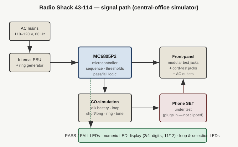
The manual’s own line is “Microprocessor-controlled for accurate diagnosis,” and the schematic identifies the part: a Motorola MC6805P2. That is an 8-bit HMOS single-chip microcontroller from Motorola’s 6805 family — CPU, a small mask ROM program store, on-chip RAM, a timer, and parallel I/O ports in one package. In 1985, at this price point, that choice is what let a Radio Shack console do go/no-go grading instead of leaving the operator to read a meter and judge for themselves.
Everything the operator experiences as “intelligence” lives in that chip’s masked program:
- It watches which test-select button is pressed and lights the LED above it.
- It sets up the correct line-side condition for that test — connect the loop, apply talk battery, switch the short/long loop network, fire the ring generator, or route the internally generated dial tone.
- It applies the PASS/FAIL threshold for the active test — the switch-hook resistance window, the cord conductor count, the dial-timing tolerances — and drives the PASS or FAIL lamp accordingly.
- It decodes dialed digits, both DTMF and pulse, and drives the numeric LED display, including the
*→ 11 and#→ 12 mapping.
The consequence for the user is that there is no calibration knob and no meter to interpret. The thresholds are baked into firmware. The operator’s job is to select the test, present the phone, and read a lamp or a number — which is exactly the workflow Vol 4 walks through. The design tradeoff, spelled out honestly in Vol 5, is that you get a verdict rather than a measurement; the console knows the switch-hook loop is inside 57–600 Ω but it will not tell you it read 210 Ω.
3.3 The front panel — where the phone connects
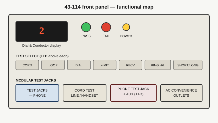
Because this is a console and not a clip-on tool, the entire interface is on the front panel: labeled modular jacks grouped by test area, a row of membrane/pushbutton test-selection keys with an LED over each, the numeric LED display, the PASS and FAIL lamps, a POWER indicator and switch, and — a detail worth noting — AC convenience outlets on the front apron.
3.3.1 The jack groups
Three functional jack areas do all the connecting:
- TEST JACKS — PHONE. The phone’s own line-cord modular plug goes here. This is the connection for the loop, dial, transmit, receive, and ring tests — the console presents its simulated line into this jack and the set answers on it.
- CORD TEST JACKS. A pair of jacks labeled for the LINE CORD and the HANDSET cord. Both ends of a single cord plug in here so the console can check the cord end-to-end, in isolation, as its own device under test.
- PHONE TEST JACK + AUX TEST JACK. The two jacks used for the answering-machine (TAD) test — a known-good phone in the PHONE jack, the answering device in the AUX jack beneath it, so the console can ring one and let it talk to the other.
There are no alligator clips and no butt-set cord. You plug the phone’s own cord into the tester; the tester supplies the line-side conditions. That is the physical embodiment of the “grades sets, not lines” identity.
3.3.2 Getting non-standard phones onto the jacks
The base jacks expect a modular line-cord plug. The manual documents the adapters for everything else:
- A wall phone is adapted with a Cat. No. 279-359 duplex adapter plus a 279-374 cord.
- A two-line phone goes through a Cat. No. 279-401 2-Line Coupler.
Cordless sets and single-line desk sets connect directly. The console explicitly may not properly test Electronic Key Systems or PABX key sets — that limit is stated in the manual and carried through the rest of this dive.
3.3.3 Preliminary setup
Before any test the manual’s sequence is: insert the AC line cord into a 110–120 V, 60 Hz source (supply spec is 105–135 VAC), press POWER, and press LONG LOOP, which is the default loop condition. Connect the phone’s line-cord modular plug to TEST JACKS — PHONE. From there the operator steps through the individual functions.
3.4 The seven-plus functions
The manual documents eight distinct operations. Short Loop / Long Loop is a condition that modifies the others rather than a standalone verdict, which is why the console is usually described as a “seven-function” tester — but it is worth treating each on its own terms.
3.4.1 Cord Test — conductor count and integrity
The cord test is the one function where the device under test is a cord, not a phone. Both ends of a handset cord, or of a line cord, plug into the CORD TEST JACKS, and the console checks the cord end-to-end.
- The numeric display shows 2 or 4 — the number of good conductors it found. A standard line cord carries an inner tip/ring pair plus an outer pair (four conductors); a handset cord is typically two.
- PASS means the cord is usable; FAIL means replace it.
- The pass criterion tolerates within-pair reversal — the two members of a pair may be swapped and the cord still passes.
- It fails on 0, 1, or 3 conductors — i.e. an open that drops the count below a good 2 or 4 — and it fails if a conductor of one pair is shorted to a conductor of the other pair — a cross between pairs.
So the cord test catches opens (missing conductors) and cross-pair shorts. This is the only tip/ring-adjacent function on the whole machine, and it is deliberately narrow: it grades a cord plugged end-to-end into the tester, not live-line polarity and not installed extension or in-wall jack wiring.
3.4.2 Loop Test — off-hook switch-hook DC resistance
With the phone’s line cord in TEST JACKS — PHONE, the loop test checks the DC resistance the set presents when it goes off-hook — the switch-hook loop closing onto the console’s simulated line.
- PASS = 57–600 Ω off-hook. That window is the set’s DC signature: enough current-limiting resistance that it is not a dead short, low enough that it will draw usable loop current on a real CO.
- FAIL = out of that range off-hook.
- On-hook, the console expects the set to return to a very high resistance — essentially an open, on the order of 10 MΩ. If the set does not restore to open on-hook, it needs service (a switch-hook that will not release, a leaky ringer path, and so on).
This is the function most often mis-described, so state it plainly: the loop test is a DC resistance go/no-go, not a current measurement. The console does not display loop current and has no ammeter. The 20–80 mA figures from Vol 2 are the real-world loop currents that result from a set’s resistance across a range of loop lengths on an actual line; here the console simply confirms the set’s off-hook resistance falls in a healthy window and its on-hook resistance goes open.
3.4.3 Dial Test — decoding each digit
The dial test verifies that the set dials correctly, and it handles both signaling methods a 1985 phone might use.
- The numeric LED display shows the digit dialed as you dial it, so the operator can confirm the set is emitting the intended digit.
- For DTMF (Touch-Tone), the star and pound keys map to numbers the display can show:
*→ 11 and#→ 12. On a tone phone the PASS/FAIL lamps stay off — the display is the result; you read out the digits and confirm they match what you pressed. - For rotary/pulse dialing, the console decodes the pulse train. The timing specs it enforces are a dial speed of 8–11 pulses per second (±0.1275) and a make/break ratio of 58–64% (±0.6%) — the standard loop-disconnect dialing window. A pulse dial that runs too fast, too slow, or with a bad make/break ratio is what a central office would choke on, and it is what the console flags.
- A wrong digit, a missing digit, or a FAIL means the dial mechanism (or the tone generator) needs service.
3.4.4 Transmit (X-Mit) Test — the microphone
The transmit test checks the handset’s transmitter — the carbon-granule (or, in later sets, electret) microphone that turns speech into a line-current variation.
- Speak into the handset mic. The PASS lamp flickers in time with speech.
- No flicker means a defective transmitter.
- The console’s internal reference for this path is −20 dBm ±5%, referenced to 600 Ω — the level the transmit signal is expected to reach.
The flicker is the whole indication: the microprocessor is watching the audio-band signal the mic injects and blinking PASS when it sees speech-level energy.
3.4.5 Receive (Rec’v) Test — the earpiece
The receive test checks the receiver — the miniature loudspeaker in the earpiece — by having the console generate a tone and asking the operator to confirm it comes through.
- Lift the handset, press RECV, and listen for a dial tone generated by the tester in the earpiece.
- Tone heard = receiver OK. No tone = defective receiver.
- The console’s reference level for this path is −26 dBm ±5%, referenced to 600 Ω.
This earpiece dial tone is the one genuinely audible result on the machine. Everything else is a lamp or a number; the receive test is the exception, and it is deliberately an operator-in-the-loop check — the human ear is the detector.
3.4.6 Short Loop / Long Loop — near versus far central office
Short and long loop are the two simulated electrical loop conditions, corresponding to a nearby central office (short loop) versus a distant one (long loop). This is the console reproducing the Vol 2 idea that a subscriber near the CO sees a short, low-loss loop while one several miles out sees a long, lossy one.
- LONG LOOP is the default, set during preliminary setup.
- The dial/transmit/receive functions are repeated under SHORT LOOP to confirm the set still works when it is presented with a close-CO condition as well as a far one.
- A SHORT LOOP or LONG LOOP LED lights to show which condition is currently active, so the operator always knows which case is being exercised.
A phone that passes on one loop condition but not the other is telling you something real about its margins — a marginal transmitter or a weak dial can work on a short, generous loop and fail on a long, starved one.
3.4.7 Ring Test — driving the ringer at two voltages
On-hook, the console drives the set’s ringer, and it does so at two selectable voltages that again map to near versus far CO.
- HIGH RING = 90 V RMS — the high-voltage ring representing a nearby central office.
- LOW RING = 45 V RMS — the low-voltage ring representing a distant one.
- A loud ring = pass. The operator listens (and watches the bell/ringer respond).
- The manual notes that some phones may legitimately not ring on Low Ring — a set with a stiff mechanical ringer or a high ringer-equivalence load can need the full high-ring voltage, and failing to ring at 45 V RMS is not automatically a fault.
Note what this is: the console is the ring generator. The 90 V RMS and 45 V RMS are voltages it produces as stimulus, not voltages it measures anywhere. It is exercising the ringer the way a CO would, at two ring voltages representing a nearby versus a distant central office.
3.4.8 TAD Test — the answering machine
The eighth operation tests a telephone answering device using the two dedicated jacks.
- A known-good phone goes into the PHONE TEST JACK; the TAD goes into the AUX TEST JACK beneath it.
- Ring the TAD with HIGH RING so it answers.
- Use X-MIT to leave a message through the known-good phone, then verify the TAD’s outgoing announcement and the message playback, and check remote features if the machine has them.
This turns the console into a miniature two-party call: the machine rings the TAD, the operator talks into a good handset the console trusts, and the TAD is graded on whether it answers, records, and plays back correctly.
3.5 Reading the machine — indicators and readout
There is no analog meter anywhere on the 43-114, and no numeric voltage, current, or resistance readout for the operator. The console communicates entirely through lamps, a small numeric display, and one audible tone:
- PASS lamp (LED) and FAIL lamp (LED) — the primary go/no-go verdict on most tests.
- Numeric LED display — the “Dial and Conductor Display.” It shows the cord conductor count (2 or 4) and the dialed digits, including 11 for
*and 12 for#. - Test-selection LEDs — one above each test button lights when that test is selected, plus the SHORT LOOP / LONG LOOP LED showing the active loop condition.
- POWER indicator — lit when AC power is present.
- The earpiece dial tone — the single “tone” the operator listens for, and only on the receive (and TAD) test. Everything else is visual.
That is the full vocabulary of the machine. A test either lights PASS, lights FAIL, shows a number, or — for receive — puts a tone in the earpiece. There is nothing to interpret on a scale, which is the entire point of a firmware-graded go/no-go console and the reason a bench tech in a phone service shop could run a set through it quickly and consistently.
3.6 How the pieces fit
The 43-114’s method is consistent across all seven-plus functions and worth restating as a single mental model. The MC6805P2 selects a stimulus or load appropriate to the test — a cord path, an off-hook loop, a pulse/tone decoder, an audio reference, a short or long loop network, a 45 or 90 V RMS ring generator, or an internally generated dial tone. The phone (or cord, or TAD) presented at the front-panel jacks responds. The firmware grades that response against a fixed threshold — 57–600 Ω, 2 or 4 conductors, 8–11 PPS at 58–64% make/break, speech-level flicker, a tone in the earpiece, a loud ring — and drives a lamp or the numeric display.
Nowhere in that chain does the console touch a live subscriber line, read a real on-hook voltage, or display a loop current. It manufactures the central office and judges the phone. Vol 4 takes this apparatus and runs an actual set through the sequence — reading the verdicts, interpreting a failure, and drawing the line between what the console can and cannot tell you.