Radio Shack 43-114 Telephone Tester · Volume 4
Radio Shack 43-114 — Vol 4: Using It
Running a set through the sequence, reading PASS/FAIL, and what it cannot test
4.1 Setting up the bench
The 43-114 is a bench console, not a field tool. Before any phone touches it, it needs mains power and a moment to settle into its default state.
Plug the AC line cord into a 110–120 V, 60 Hz outlet — the supply spec is 105–135 VAC. This is the whole power story: there is no battery, and the unit draws nothing from a phone line. Press POWER; the POWER indicator lights to confirm mains is present. At roughly 13 pounds the box stays put on the bench, which is exactly where it is meant to live.
Out of reset the tester comes up in LONG LOOP. That default matters, because LONG LOOP is the reset condition and simulates a distant central office. Both loop conditions have to be run, though — a set can pass one and fail the other (as this volume covers below), so neither substitutes for the other. The SHORT LOOP / LONG LOOP LED shows which condition is active; confirm it reads LONG LOOP before starting.
The front apron carries AC convenience outlets. Any phone or answering machine that needs household AC to run — a cordless base, a TAD — plugs into those outlets so it is powered while under test. This keeps the AC-powered accessory and the tester on the same bench without a second wall outlet.
4.1.1 Getting the phone connected
The phone under test plugs into the tester by its own cord — there are no clips, no butt-set, no alligator leads. The tester provides the simulated line; the set plugs in and is graded.
- A standard single-line desk phone: its line-cord modular plug goes into TEST JACKS – PHONE.
- A wall phone (with the keyhole mount rather than a line cord): adapt it with the Cat. No. 279-359 duplex adapter plus a 279-374 cord to present a modular plug the tester can take.
- A two-line phone: bring it in through a 279-401 2-Line Coupler so each line appears on the tester one at a time.
Get the physical connection right before pressing any test button. Most spurious FAILs at the start of a session are a plug not fully seated, not a bad phone.
4.2 The test sequence
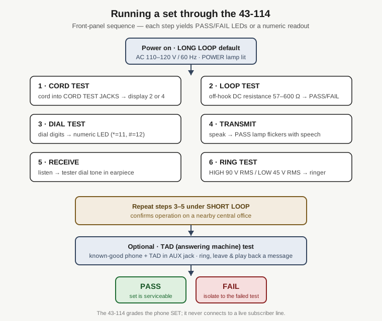
The functions are meant to be run as a battery, roughly in the order below, with LONG LOOP selected first and then a repeat of the dial, transmit, and receive tests under SHORT LOOP. Each function reports either a PASS/FAIL lamp or a number on the LED display — never a meter reading.
4.2.1 — Cord test
The cord test stands slightly apart from the rest: it grades a cord, not the phone’s electronics. Unplug the line cord (or the handset cord) and plug both of its ends into the CORD TEST JACKS.
Read the numeric display. It shows the number of good conductors it found: 2 for a two-conductor cord (the inner tip/ring pair), 4 for a four-conductor cord (inner pair plus the outer pair). A PASS means the cord is usable; a FAIL means replace it.
What makes it PASS or FAIL:
- A good 2- or 4-conductor cord passes. The two members of a pair may be reversed end-to-end and still pass — the test does not care about within-pair orientation.
- It fails on 0, 1, or 3 conductors — an open somewhere in the cord.
- It fails if a conductor of one pair is shorted to a conductor of the other pair — a cross between pairs.
Run this first when a set misbehaves broadly. A single open or crossed cord conductor will cascade into apparent loop, dial, transmit and receive failures downstream, and chasing those before clearing the cord wastes time.
4.2.2 — Loop test
Plug the phone’s line cord into TEST JACKS – PHONE. The loop test grades the DC resistance the set presents when it goes off-hook — its switch-hook loop signature to the simulated CO.
Take the set off-hook. PASS = 57–600 Ω off-hook; a resistance outside that window is a FAIL. This is a resistance go/no-go, not a current reading — the tester shows a PASS or FAIL lamp, never a number of milliamps. (The 20–80 mA figures that come up around loop current are the real-line phenomena the box simulates, covered in Vol 2; they are not values it displays.)
There is a second half to this test worth watching. Put the set back on-hook. The tester expects the loop to return to an open — on the order of 10 MΩ. If the set does not restore to that open circuit on-hook, it needs service even though the off-hook number was fine; something in the switch-hook or network is not releasing.
4.2.3 — Dial test
The dial test verifies each dialed digit or character, and it is the one function that turns the numeric LED display into the primary readout. It handles both dialing methods a 1980s set might use: DTMF (Touch-Tone) and rotary/pulse.
Dial a digit. The display shows the digit it decoded. Work through 0–9 and confirm each one reads back correctly. For the two non-numeric DTMF keys the display uses a code: * reads as 11, and # reads as 12. On a tone (DTMF) phone the PASS/FAIL lamps stay off during this test — the number on the display is the result, so read the display, not the lamps.
A wrong digit, a missing digit, or a FAIL points at the dial: a bad keypad or DTMF encoder on a tone set, or worn/misadjusted pulse contacts on a rotary set. Internally the tester holds the pulse set to tight windows — dial speed 8–11 PPS (±0.1275) and make/break ratio 58–64% (±0.6%) — so a rotary phone whose governor or contacts have drifted will read wrong or fail here.
4.2.4 — Transmit test
Lift the handset and speak into the mouthpiece. On a good transmitter the PASS lamp flickers in time with your speech — it is following the audio energy the carbon-granule transmitter is putting onto the line. No flicker means a dead or open transmitter.
This is a functional check, not a level measurement. The tester’s internal reference sits at −20 dBm (±5%, referenced to 600 Ω), but the operator sees a flickering lamp, not a dB number. Speak normally and steadily; a mumble can under-drive the indicator and read as a fault that is really just a quiet talker.
4.2.5 — Receive test
With the handset still off-hook, press RECV and listen in the earpiece. The tester generates a dial tone and sends it to the receiver. Hearing the tone means the receiver (earpiece) works; silence means it is dead.
That earpiece dial tone is the one audible result the operator judges by — everything else on this box is a lamp or a number. The tone sits at an internal reference of −26 dBm (±5%, referenced to 600 Ω), but again there is nothing to read: you either hear it or you don’t. Listen in a quiet spot on the bench so a weak-but-present receiver is not mistaken for a dead one.
4.2.6 — Ring test
Put the set back on-hook — the ringer is an on-hook function. The tester drives the phone’s ringer with an AC ringing voltage, and there are two levels:
- HIGH RING = 90 V RMS, simulating a nearby central office.
- LOW RING = 45 V RMS, simulating a distant one.
A good loud ring is a pass. Test both levels. One caveat that keeps a good phone from being condemned: some phones may legitimately not ring on LOW RING. Failure to ring on HIGH RING is the real red flag; a set that rings on HIGH but not LOW is usually fine on any normal line.
4.2.7 Repeating under SHORT LOOP
Steps 3–5 — dial, transmit, receive — get repeated with SHORT LOOP selected. LONG LOOP has already exercised the set against a distant CO; SHORT LOOP confirms it also behaves against a close one, where loop current is higher and the electrical conditions differ. Press SHORT LOOP (watch the loop LED change), then run the dial, transmit, and receive tests again. A set that passes both loop conditions is good across the range of central-office distances the box models. The ring test’s own near/far behavior is handled separately by HIGH RING and LOW RING, which are independent of the SHORT/LONG LOOP switch — so the ringer does not need re-running under SHORT LOOP.
4.3 Reading the indicators
The 43-114 has no analog meter and puts no voltage, current, or resistance number in front of the operator. Everything is either a lamp or the small numeric display. Knowing which readout owns which test is half of using the box correctly.
- PASS lamp / FAIL lamp — the primary go/no-go verdict for most tests: loop, transmit, receive, ring. On the transmit test the PASS lamp flickers rather than sitting solid — that flicker is the signal.
- Numeric LED display (“Dial and Conductor Display”) — the primary readout for the two tests that produce a value: the cord test (2 or 4 conductors) and the dial test (the digit dialed, with
*=11 and#=12). On a DTMF phone during the dial test the PASS/FAIL lamps are off by design, so the display is the only result. - Test-selection LEDs — an LED lights above whichever test button you pressed, so you always know which function is armed.
- SHORT LOOP / LONG LOOP LED — shows which central-office condition is active. Check it whenever a result surprises you; running a test under the wrong loop condition is an easy mistake.
- POWER indicator — mains present. If it is dark, nothing else on the panel means anything.
The single audible cue is the receive-test dial tone in the earpiece. There is no beeper announcing PASS or FAIL; the verdicts are visual.
4.4 Interpreting a failure
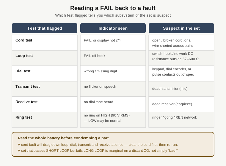
A FAIL on the 43-114 is a pointer, not a diagnosis. Because each function exercises a specific part of the set, the test that flagged tells you where to look inside the phone.
- Cord test FAIL / wrong conductor count — the cord is open or cross-shorted. Replace the cord and re-run the battery; do not touch the phone’s electronics yet.
- Loop test FAIL off-hook — the set’s off-hook DC resistance is outside 57–600 Ω. Suspect the switch-hook contacts or the network. A set that reads fine off-hook but won’t return to an open on-hook has a switch-hook or network that isn’t releasing.
- Dial test wrong/missing digit — the keypad or DTMF encoder (tone set) or the pulse governor/contacts (rotary set). Remember
*=11 and#=12 are correct readings, not faults. - Transmit test, no flicker — dead transmitter. Rule out a quiet talker first by speaking up.
- Receive test, no tone — dead receiver. Rule out bench noise first.
- Ring test, no ring on HIGH — ringer, gong, or ringer network. No ring on LOW only is often normal.
The discipline that keeps this honest: run the whole battery before condemning a part. A single upstream fault — a bad cord above all — drags several downstream tests to FAIL at once. Clear the cheapest, most-upstream cause first, re-run, and let the pattern of what clears and what remains isolate the real fault. And treat a set that passes SHORT LOOP but fails LONG LOOP as marginal on a distant CO, not simply broken — that is real information about where the phone will and won’t work.
4.5 What it can and cannot test
The 43-114 grades telephone sets and answering machines. Being clear about the boundary of that scope is what keeps it from being misused as something it isn’t.
4.5.1 What it handles
- Single-line sets — the core case, tone or pulse, plugged straight into the phone jack.
- Rotary/pulse and Touch-Tone (DTMF) dialing — the dial test decodes both.
- Cordless phones — supported; the base plugs in and can draw AC from the front convenience outlets while under test.
- Two-line phones — supported via adapter (the 279-401 2-Line Coupler), each line tested in turn. This is the “adaptable,” conditional case, not a native mode.
- Telephone answering devices (TADs) — the dedicated TAD test uses the PHONE TEST JACK for a known-good phone and the AUX TEST JACK beneath it for the machine. Ring the TAD with HIGH RING, use the transmit function to leave an outgoing message, then verify the outgoing announcement, playback, and any remote features. This exercises the answering machine as a system rather than grading it on a single lamp.
4.5.2 What it cannot do
- It is not a line or loop tester. It never clips onto a live subscriber pair. It does not display tip/ring polarity, does not read the actual on-hook line voltage, and does not show live loop current. It is the source of simulated central-office conditions, and it grades the phone against them. The only tip/ring-adjacent function is the cord test, which checks a cord’s conductor count and integrity — not a live line’s polarity.
- It is not a butt-set or test handset. You cannot monitor or place a call on a real line with it. There is no talk battery to an outside line and no dial-out to a real CO.
- It is not metrology. Results are PASS/FAIL lamps and a small numeric display — no calibrated voltage, current, or resistance number for the operator. The internal thresholds (57–600 Ω off-hook, the ring voltages, the dB references) are the tester’s own criteria, not values it reports out.
- It may not test Electronic Key Systems or PABX key sets. This is called out explicitly. The box models a plain single-line central office; multi-line key/PABX sets expect signaling it does not provide, and results on them cannot be trusted.
The one-line summary to keep in mind while using it: the 43-114 tells you whether a phone is good, by pretending to be the phone company. It says nothing about the wire in the wall. Vol 5 puts numbers and limits side by side in a quick-reference and sets that scope against a real butt-set and line analyzer.