Radio Shack 43-114 Telephone Tester · Volume 5
Radio Shack 43-114 — Vol 5: Cheatsheet + Context
Quick reference, the device’s place, and the honest limits
5.1 What this volume is for
Volumes 1 through 4 built the picture from the ground up: what the 43-114 actually is (Vol 1), the POTS phenomena it leans on (Vol 2), the seven-odd functions and the MC6805P2 that runs them (Vol 3), and the bench procedure for grading a set (Vol 4). This volume is the card you tape to the underside of the lid — the numbers, the sequence, and an honest accounting of where this box stops being useful and a butt-set or a line analyzer starts.
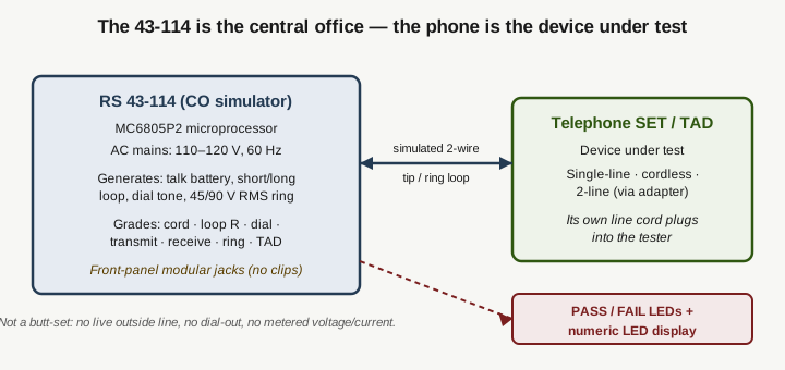
One sentence to keep everything oriented: the Radio Shack 43-114 (Tandy, © 1985, made in U.S.A.) is a ~13 lb, AC-mains-powered, microprocessor-controlled benchtop console that simulates a central office and grades a telephone set (or answering machine) PASS/FAIL. It is the CO side of the wire. The phone is the device under test. It does not clip onto a live subscriber pair and it never displays a measured line voltage or loop current.
5.2 Quick reference
5.2.1 The functions at a glance
Table 1 — The functions at a glance
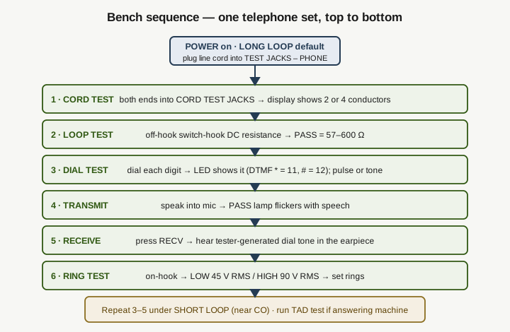
| # | Function | What it exercises | PASS criterion / readout |
|---|---|---|---|
| 1 | Cord test | Conductor count + integrity of a line or handset cord, plugged end-to-end into CORD TEST JACKS | Numeric display shows 2 or 4 conductors; a good 2- or 4-conductor cord passes (within-pair reversal tolerated). FAILS on 0, 1, or 3 conductors, or a conductor of one pair shorted to the other pair |
| 2 | Loop test | Off-hook switch-hook DC resistance of the set | PASS = 57–600 Ω off-hook. On-hook the set should return to ~10 MΩ (open); if it doesn’t restore, service the switch-hook |
| 3 | Dial test | Each dialed digit/character; rotary/pulse or DTMF | Numeric display echoes the digit dialed. DTMF * → 11, # → 12. Pulse spec 8–11 PPS ±0.1275; make/break 58–64% ±0.6% |
| 4 | Transmit (X-Mit) | The handset transmitter (mic) picking up speech | PASS lamp flickers with speech; no flicker = defective transmitter. Level −20 dBm ±5% ref 600 Ω |
| 5 | Receive (Rec’v) | The handset receiver (earpiece) reproducing a tone | Lift handset, press RECV, hear a tester-generated dial tone in the earpiece; silence = defective receiver. Level −26 dBm ±5% ref 600 Ω |
| 6 | Short / Long Loop | Near-CO vs. distant-CO electrical loop condition | Selection LED shows which loop is active; tests 3–5 are re-run under SHORT LOOP to confirm operation on a close office |
| 7 | Ring test | The set’s ringer, driven on-hook | LOW RING = 45 V RMS (distant CO), HIGH RING = 90 V RMS (nearby CO). Loud ring = pass; some sets legitimately won’t ring on Low |
| 8 | TAD test | An answering machine’s ring-answer, outgoing message, record/playback | Known-good phone to PHONE TEST JACK, TAD to AUX TEST JACK; ring with HIGH RING, X-MIT a message, verify OGM + playback |
5.2.2 The numbers worth memorizing
Table 2 — The numbers worth memorizing
| Parameter | Value | Note |
|---|---|---|
| Loop-test PASS window | 57–600 Ω | Off-hook DC resistance — a resistance go/no-go, not a current reading |
| On-hook restore | ~10 MΩ (open) | The set must return the loop to open when hung up |
| Low Ring | 45 V RMS | Generated by the tester (distant-CO simulation) |
| High Ring | 90 V RMS | Generated by the tester (nearby-CO simulation) |
| Cord conductor display | 2 or 4 | Inner tip/ring pair + outer pair |
| DTMF star / pound | * = 11, # = 12 | Two-digit codes on the numeric LED |
| Pulse dial speed | 8–11 PPS ±0.1275 | Rotary/pulse timing window |
| Pulse make/break | 58–64% ±0.6% | Percent-break window |
| Transmit level | −20 dBm ±5% | Referenced to 600 Ω |
| Receive level | −26 dBm ±5% | Referenced to 600 Ω |
| Power input | 110–120 V, 60 Hz (supply spec 105–135 VAC) | AC mains only; not battery, not line-powered |
| Weight | 13 lb | Benchtop console |
5.2.3 POTS reference values (what it simulates, not what it reads)
These are the real-line phenomena the 43-114 imitates. They come from the manual’s own terminology page — the device teaches them and generates analogs of them, but it never displays a measured value for any of them.
Table 3 — POTS reference values (what it simulates, not what it reads)
| Phenomenon | Nominal value | Role here |
|---|---|---|
| On-hook talk battery | ~48–50 V DC | Cited as background; the tester provides a loop, not a metered voltage |
| Loop current vs. distance | ~80 mA (short loop) down to ~20 mA (long loop) | Explains Short/Long Loop selection; never shown as a number |
| Ringing (real POTS) | ~90 V RMS AC at ~20 Hz on DC | Matches the tester’s High Ring stimulus |
| Subscriber loop | 2-wire tip/ring pair | The pair the tester emulates end-to-end |
5.2.4 Adapters and jacks
Table 4 — Adapters and jacks
| Item | Cat. No. | Use |
|---|---|---|
| Duplex adapter | 279-359 | Adapting a wall (hard-wired) phone to the modular test jack |
| Modular cord | 279-374 | Companion cord for the wall-phone adaptation |
| 2-Line coupler | 279-401 | Testing a 2-line phone |
Front-panel jack groups: TEST JACKS – PHONE (the phone’s line cord), CORD TEST JACKS (a bare LINE CORD or HANDSET cord, both ends), and PHONE TEST JACK + AUX TEST JACK (the TAD pair). Everything plugs in; there are no alligator clips and no butt-set cord.
5.3 Where this box sits in the shop
5.3.1 The job it was built for
The 43-114 is a service-counter triage tool for customer-owned telephone equipment. Its intended audience, per the manual, was “Office Equipment Sales/Service organizations” and “Telemarketing professionals” — shops that sold and repaired phones and answering machines and needed to settle one question fast: is the fault in this set, or is it out on the line? The manual’s own pitch is to “avoid needless outside repairs.” Before a shop dispatched a technician to a customer’s premises, or before it accepted a set for bench repair, it could drop the phone onto the 43-114, run the sequence, and get a PASS/FAIL verdict on the instrument itself in a couple of minutes.
That framing explains every design choice. It is heavy and AC-powered because it lives on a bench, not in a lineman’s pouch. It has front-panel modular jacks and convenience AC outlets because the workflow is “set the phone down next to it and plug in.” It grades PASS/FAIL rather than metering because a counter clerk, not an RF engineer, is the operator. It simulates short and long loops and high and low ring because a set that works on a nearby CO can still fail on a distant one, and the shop needs to catch that without driving to the far end of a real loop.
5.3.2 The moment it belongs to
1985 was near the peak of the environment this tool was made for. Divestiture had broken up the Bell System in 1984, and for the first time the telephone on a customer’s desk was their property to buy, own, and get repaired at an independent shop rather than lease from the phone company. That created exactly the market the 43-114 served: a flood of customer-owned single-line sets, cordless phones, and answering machines, all needing a quick “is it the phone?” answer at a service counter that had no direct relationship with the telco. Tandy, with a Radio Shack storefront in every strip mall, was ideally placed to sell both the phones and the tester that graded them.
The microprocessor inside — a Motorola MC6805P2 — also dates it precisely. Putting an 8-bit micro in charge of a consumer-service instrument in 1985 was a modern, cost-driven move: one small controller sequencing the tests, driving the LED display, decoding dialed digits, and rendering PASS/FAIL was cheaper and more flexible than a rack of discrete analog comparators. It is a very 1980s answer to a very post-1984 problem.
5.3.3 Sibling tools it is not
It is worth stating plainly what other telco tools do, because the 43-114 is routinely mistaken for each of them:
- A butt-set (Harris TS22, Fluke TS54 Pro and kin) is a rugged handheld test telephone. It clips onto a live subscriber pair with a butt-in cord, draws talk battery from the real line, monitors or places calls, and lets a lineman work the outside plant. The 43-114 does none of this — it has no clips, provides no talk battery to an outside line, and cannot dial the CO.
- A line/loop tester or line analyzer clips onto a live pair and measures it: tip/ring polarity, on-hook voltage, loop current, loop resistance to the far end, noise, longitudinal balance. The 43-114 measures none of these on a live line. Its Loop test grades the set’s off-hook resistance, and every “line” condition it presents is one it generated itself.
- A cable/wiring tester checks installed premise wiring — extension jacks, house pairs, cross-connects. The 43-114’s Cord test checks a cord plugged end-to-end into the tester, not wiring in the wall.
Same wires, tip and ring, three different jobs. The 43-114 owns exactly one of them: grading the instrument.
5.4 The honest limits
5.4.1 What it genuinely cannot do
- It does not touch a live line. There is no outside-plant connection, no talk battery fed to a real pair, no dial-out to a central office. It is the source of simulated conditions; the real network is never in the loop.
- It gives no metered numbers. No analog meter, no voltage readout, no current readout, no resistance readout. The only numeric display is the two-digit conductor count / dialed-digit field. Every threshold — the 57–600 Ω loop window, the ring voltages, the dial timing — lives inside the firmware as a go/no-go boundary, invisible to the operator. You learn that a set failed, not by how much.
- No live-line tip/ring polarity. There is no polarity LED and no polarity test. The only tip/ring-adjacent function is the Cord test, which counts conductors and catches cross-pair shorts on a cord — it tolerates within-pair reversal and says nothing about live-line polarity.
- No loop-current display. The 20–80 mA figures are background teaching only. The nearest real function is the Loop test’s off-hook resistance verdict.
- Key systems and PABX are out of scope. The manual states outright the unit “may not properly test Electronic Key Systems or PABX Key Sets.” It is a single-line-set tool (2-line via the 279-401 coupler, cordless supported).
- It is bench-bound. ~13 lb and mains-only. This never leaves the shop.
5.4.2 What that means in practice
The 43-114 answers one question well and refuses to answer any other. If a customer’s single-line phone or answering machine is dead or misbehaving, the 43-114 will tell you, quickly and without a truck roll, whether the fault is inside that instrument — a bad cord, a stuck switch-hook, a dead dialer, a failed transmitter or receiver, a ringer that won’t answer a distant-CO ring. That is a genuinely valuable and specific capability, and it was the right tool for a 1980s service counter drowning in newly customer-owned phones.
But the moment the question becomes “what’s wrong with the line,” this box has nothing to offer. It cannot tell you the pair is reversed, or the loop is too long, or there’s a ground fault or excessive noise or crossed pairs in the wall. For any of that you reach for a butt-set to work the live pair or a line analyzer to measure it. Knowing which question you’re actually asking is the whole art of using this instrument correctly — and it is exactly the distinction its “Telephone Tester” name blurs.
5.5 POTS-sunset context — why it stays in the kit
The world the 43-114 was built for is largely gone. US incumbent carriers have spent the last decade-plus retiring copper-pair voice, migrating subscribers onto VoIP and fiber, and the customer-owned single-line desk phone is no longer the default household object it was in 1985. A go/no-go tester for POTS instruments is, on its face, a solution to a shrinking problem.
It earns its bench space anyway, for three reasons:
- POTS is not fully dead. A stubborn, safety-critical tail of copper voice survives: alarm-system circuits, elevator emergency phones, fax-only lines, and rural lines still riding real loops. A working single-line set on one of those lines is exactly what the 43-114 was made to grade.
- The generated conditions have other uses. A box that sources a clean simulated 2-wire loop, short/long-loop current behavior, and 45/90 V RMS ring is a useful stimulus source on the bench for understanding, and roughly exercising, other 2-wire and low-voltage signaling gear.
- It is a teaching instrument. For anyone learning how a subscriber loop, a switch-hook, DTMF versus pulse dialing, and telco ringing actually behave, having the CO side in a box you can probe — and a manual whose terminology page lays out the real values — is a better classroom than a live line you’re not supposed to touch.
It is a reference instrument now, not a primary tool for any active job. But it is a clean, self-contained embodiment of how the POTS local loop worked, and that is worth keeping intact.
5.6 The card, condensed
If nothing else survives from these five volumes, keep this:
- It simulates a central office; the phone is the device under test. Front-panel jacks, phone plugs in with its own cord.
- Seven-odd functions: cord, loop resistance, dial, transmit, receive, short/long loop, ring, TAD.
- Loop test = off-hook resistance, 57–600 Ω — not current, not voltage.
- Ring: Low 45 V RMS / High 90 V RMS. Cord display: 2 or 4. DTMF
*=11,#=12. - Verdict is PASS/FAIL LEDs + a numeric display. No analog meter, no metered voltage or current, no live-line polarity.
- AC-mains, ~13 lb, bench-only. Single-line + cordless yes; 2-line via adapter; key systems / PABX no.
- It is not a butt-set, a line/loop tester, or a cable tester. It grades sets, not lines.