Simpson 260 Series 8 · Volume 1
Simpson 260 — Vol 1: Overview & Why the 260 Still Earns Bench Space
A 50 µA needle, a mirrored dial, and 20,000 Ω/V of stubborn relevance across nine series and nine decades.
1.1 Why an analog meter still earns bench space
Set a modern autoranging DMM next to a Simpson 260 and the DMM wins on paper — better basic accuracy, higher input impedance, a display you can read without doing scale math. So why does the 260 stay on the bench instead of in a drawer? Because a swinging needle and a jumping digital display are answering two different questions, and a surprising amount of bench work needs the needle’s answer.
-
Rate and direction, not just magnitude. A needle shows you which way a value is moving and how fast — peaking a slug-tuned IF transformer, nulling a bridge, dip-finding a resonance, walking a bias trimmer toward center. On a DMM those are three or four flickering digits refusing to hold still long enough to tell you if you just overshot. On the 260 it’s a needle sweeping smoothly toward (or past) a point, and your hand knows to stop the instant it reverses. This is the single biggest reason service techs kept 260s in service long after cheap DMMs became available: alignment work is a rate-of-change problem, and analog meters are rate-of-change instruments.
-
Mechanical smoothing of a noisy signal. The moving coil in a D’Arsonval movement has real mass and a real spring constant — it is a mechanical low-pass filter. A twitchy, RFI-laced, or slightly unstable reading settles into a readable average on a needle; the same signal makes a DMM’s last two digits flicker uselessly. You don’t need to add a scope or a cap across the DMM leads to get a stable-enough reading — the 260’s inertia does it for free.
-
The ohms ranges drive a known current, which makes them a component tester, not just a resistance readout. Every ohms range pushes a fixed nominal current through the unknown (125 mA on R×1, 1.25 mA on R×100, 75 µA on R×10,000 — Vol 3 §5 derives these from the two internal batteries). That’s enough current to forward-bias a silicon or germanium junction. Touch the ohms leads across a diode one way, then the other, and you’re not measuring “resistance” in any meaningful sense — you’re watching a junction conduct in one direction and block in the other, which is exactly the go/no-go test a bench tech needs. The same trick reads a transistor’s B-E and B-C junctions, and touching the ohms leads across a capacitor makes the needle kick toward zero and creep back as the cap charges from the internal battery — a visible, physical demonstration of charge that a DMM’s ohms function (which uses a much smaller test current, often too small to forward-bias a junction cleanly, and updates as a numeric readout rather than a kick-and-settle sweep) doesn’t give you nearly as intuitively.
Note — this only works because the 260’s ohms function is a real current source referenced to an internal battery, not a bridge or a constant-voltage probe. See Vol 3 §5 and Vol 4 §4 for the full ohms-circuit theory and the diode/transistor/cap test procedures.
-
No warm-up, and no battery dependency for volts or current. The DC and AC voltmeter ranges and the current ranges are passive — a resistive multiplier ladder and an Ayrton shunt feeding the movement directly (Vol 3 §3–§4). There’s no amplifier to warm up, no internal reference to settle, and critically no battery required to read volts or amps. The two batteries inside a 260 (Vol 2 § “battery/fuse” discussion, Vol 5 throughout) exist only to power the ohms ranges (and, on a P model, the overload relay). A DMM with a dead 9 V battery is a paperweight. A 260 with a dead D-cell will still read every volt and amp range perfectly — only ohms goes out.
-
Lower input impedance can be a feature, not a limitation. 20,000 Ω/V DC sounds low next to a DMM’s flat 10 MΩ, and on a genuinely high-impedance node (a tube grid, a screen bleeder, an AVC line) that low impedance loads the circuit enough to shift the reading — which is exactly why the bench also keeps a VTVM around (see below). But on a low-impedance power node, that same 20 kΩ/V load is usefully “heavy”: it’s enough to sink stray induced AC, capacitive leakage, and ghost/phantom voltage from an unpowered or floating conductor sitting near live wiring. A 10 MΩ DMM will happily display 40, 60, even 90 V of “phantom” voltage on a disconnected wire that’s simply picking up capacitive coupling from an adjacent hot conductor — a classic false-positive that trips up techs new to a DMM. Load that same wire with a 260’s 20 kΩ/V input and the phantom voltage collapses toward zero, because there’s nothing behind it to actually source current. The 260’s “worse” spec is, on this specific class of measurement, the more honest answer.
-
Rugged, RFI-tolerant, and readable anywhere. No LCD to wash out in direct sun, no digital front end to desensitize near a transmitter or a switching supply, no firmware to glitch. A mechanical movement in a phenolic case shrugs off the kind of RF-dense or bright-outdoor environment that gives a DMM trouble, and it responds instantly — there’s no sample-and-hold cycle to wait through.
None of this makes the analog 260 a replacement for a modern DMM — see “What the 260 is not,” below. It makes it a different instrument for a different class of question, and that’s why it still earns a spot on the bench next to whatever autoranging DMM lives there too.
1.1.1 Concrete bench scenarios where the needle wins
It’s easy for “the needle is better for rate-of-change work” to stay an abstraction, so here are the specific jobs where reaching for a 260 instead of a DMM is a deliberate choice, not a habit:
- Tuning an IF transformer or antenna coil. Clip the 260 across a detector or AGC test point, slug the core, and watch the needle climb toward a peak. The instant it starts to fall back, you’ve gone past the peak — turn back a hair. A DMM forces you to watch a two- or three-digit number change fast enough that you can’t tell peak-from-past-peak without over-tuning and walking it back repeatedly.
- Nulling a bridge (capacitance bridge, resistance bridge, a simple Wheatstone setup on the bench) — the null is, by definition, a minimum, and a needle collapsing toward center-zero is unambiguous in a way that “0.001 V… 0.000 V… 0.001 V” flicker is not.
- Checking a filter cap or an electrolytic’s rough health on the ohms ranges. Touch the leads across a good electrolytic on R×1 or R×100 and the needle kicks hard toward zero ohms, then creeps back toward infinity as the cap charges from the 260’s internal battery. A shorted cap kicks and stays at zero. An open or dried-out cap barely kicks at all. It’s a five-second go/no-go check that doesn’t require pulling the part or reaching for a capacitance meter.
- Sorting a bin of diodes or verifying an unmarked rectifier’s polarity. R×1 both directions — low reading one way, near-infinite the other — is the junction doing its job. Two low readings is a shorted junction; two high readings is an open one. This is the exact test described in the ohms-driven component-testing bullet above, done in practice.
- Checking for AC line hum or induced voltage on a “dead” chassis before reaching in with both hands.
A 260 on its lowest AC range loads out spurious induced voltage the way a DMM won’t, so a real hazard
reads as a real hazard and a phantom coupling reads close to zero — see the ghost-voltage bullet above,
and the safety cross-reference to
_shared/legal_ethics.md.
1.2 What the Simpson 260 is
The Simpson Model 260 is a hand-held analog volt-ohm-milliammeter (VOM) — the classic American field multimeter, in continuous production (with running design changes) from the late 1930s into current-day manufacture. Its identity is fixed by three numbers that appear on every series:
Table 1 — current-day manufacture. Its identity is fixed by three numbers that appear on every series
| Parameter | Value | Confidence |
|---|---|---|
| DC voltmeter sensitivity | 20,000 Ω/V | [CONFIRMED — primary, Series 8/8P Table 1-1] |
| AC voltmeter sensitivity | 5,000 Ω/V | [CONFIRMED — primary, Series 8/8P Table 1-1] |
| Meter movement | D’Arsonval moving-coil, 50 µA full scale (250 mV drop at FS) | [CONFIRMED — primary] |
| Rated circuit-to-ground voltage | 1000 V AC/DC max (per ANSI C39.5) | [CONFIRMED — primary, Series 8/8P] |
| Ohms ranges | R×1, R×100, R×10,000 (rotary function+range switch) | [CONFIRMED — primary] |
| Weight / size (Series 8) | ~3 lb; 5½″ × 7″ × 3″ | [CONFIRMED — primary] |
That 20,000 Ω/V DC figure is the meter’s whole identity: it was among the first VOMs sensitive enough to be broadly useful on the vacuum-tube and early-transistor circuits of its era without loading them into uselessness, and it stayed the de facto standard sensitivity figure that competitors were compared against for decades. [LIKELY — secondary]
Jeff’s bench holds two of them — a late-production Series 8 (mirror-standard, taut-band, diode movement protection) and a Series 6P (the first series with the modern D-cell + 9 V battery combination, taut-band standard, and a front-panel overload reset button). Vol 2 walks the full genealogy that separates those two units by roughly two decades of running changes; Vol 5 uses both as refurbishing case studies, with the 6P’s corroded battery holders — the actual repair Jeff performed — as the centerpiece.
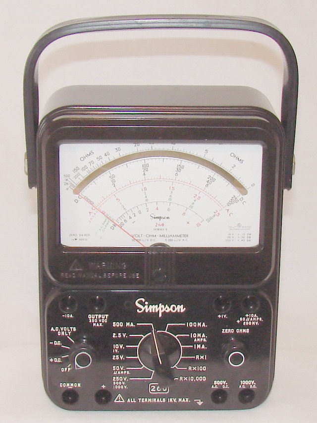
The 260 is still in production today. Simpson Electric (Lac du Flambeau, WI) currently sells the 260-8, 260-8P, a mining/construction variant (260-8MCS), and the safety-rated 260-9S / 260-9SP — the same basic 50 µA / 20,000 Ω/V architecture Jeff’s Series 8 uses, in a still-current catalog line. [CONFIRMED — simpsonelectric.com product pages]
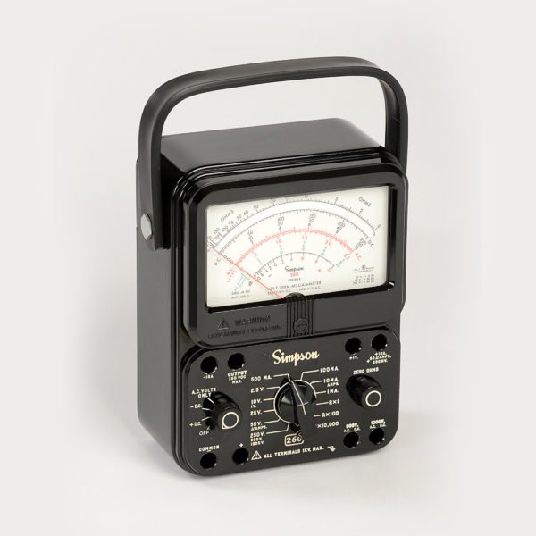
1.2.1 The three things that make a 260 a 260
Across every series covered in this dive, three design elements stay constant while everything around them changes generation to generation. It’s worth naming them once, up front, because Vol 2 and Vol 3 each spend a volume’s worth of detail on how they evolved:
- The 50 µA D’Arsonval moving-coil movement. Every series, from the pin-jack original to today’s 260-9SP, is built around a 50 µA full-scale movement. What changes is the suspension — pivot-and-jewel bearings through the mid-1960s, taut-band suspension debuting on the 5M (~1969) and standard from Series 6 (~1973) on — and whether the dial behind it is mirror-backed (debuting on the 4M, standard from Series 8). Vol 2 §3–§4 and Vol 3 §2 cover both threads in full; the short version worth remembering here is that mirror and taut band are two separate upgrades that arrived one series apart, not a single “modernization” event.
- The rotary function/range switch. All nine series select function and range with a rotary switch — never a lever, never a set of pushbuttons. What changes is the switch’s construction (hand-wired contacts on the earliest series, a plastic wafer switch on a PCB from Series 3 on) and how many positions it carries as ranges were added (the 0–25 V AC/DC range, for instance, is new to Series 8).
- The ohms function referenced to two internal batteries. A 1.5 V cell serves the R×1 and R×100 ranges; a higher-voltage cell serves R×10,000. The values and cell types of those two batteries changed several times across the genealogy — Vol 2’s per-series table and Vol 5’s battery-complement table both track it — but the two-battery, three-multiplier architecture itself has been constant since the original 260.
1.2.2 Leads, jacks, and the accessory ecosystem
The 260 reads through a pair of test leads plugged into recessed panel jacks — pin-type leads on the earliest series, banana-jack leads from Series 3 on, and polarity-keyed reverse-banana “safety” jacks from Series 7 on (Vol 2 §6 uses this progression as one of the fastest series-ID tells). The current-production lead set is Simpson Catalog No. 00043 — 48″ combination probe-tip leads with removable, rubber-sleeved alligator clips, rated 1000 V AC/DC / 10 A, and fitted to the 260-7/8/9 family (older-series leads are Cat. No. 00125 for Series 3–6 and Cat. No. 02055 for the earliest units). Beyond the standard 1000 V range, a dedicated 5000 V HV probe plugs into its own panel jack to extend both the DC and AC voltmeter ladders to 5000 V — it is an external accessory, not a switch position, and Vol 3 and Vol 4 both return to that distinction because it’s a common point of confusion for anyone used to a DMM’s single rotary-selects-everything layout. Vol 4 covers the full operating procedure for both the standard leads and the HV probe; Vol 5 covers lead/jack sourcing as part of parts availability today.
1.3 A field VOM, not a lab reference: historical placement
- Patent 2,051,399, dated August 18, 1936, appears printed above the ohms scale on the original meter face — the usual basis for calling 1936 the 260’s “birth year.” That is the design/patent date, not a shipping date. [CONFIRMED — visible on the instrument]
- The earliest confirmed paperwork — operating instructions — is dated July 20, 1939; radiomuseum.org lists the original 260’s production span as 1939–1951. The best-supported synthesis: design in 1936, first documented sales and shipping ~1939, with the original body style remaining on the market into the 1940s–1951 range depending on source. [LIKELY — synthesized from conflicting sources, see Vol 2 §1 for the full conflict record]
- Simpson’s own company history credits the 260 as the VOM “that thousands of military personnel used during World War II” — a manufacturer-confirmed claim of generic wartime military use. This volume deliberately does not repeat the popular claim that the 260 was an “official U.S. Navy standard” or a “Bell System standard” instrument — that specific institutional claim could not be verified in any primary source during research for this deep dive, however plausible it sounds next to the confirmed WWII-military claim. [CONFIRMED generic military use; specific institutional-standard claims NOT FOUND — see Vol 2 §1, §5]
- The 260 has been in some form of continuous production ever since — the original plus eight numbered series, Series 2A through 9SP (plus sub-variants), spanning pin-jack hand-wired construction on the un-numbered 1939 original to a current PCB-based, taut-band, mirrored-dial instrument sold new today. Few instruments of any kind can claim an 85+ year unbroken production run under the same model number.
1.4 Bench role: when to reach for the 260 vs. a VTVM
The 260’s 20,000 Ω/V DC input impedance is excellent for a passive meter but is nowhere close to a vacuum-tube voltmeter’s typical 10–11 MΩ fixed input impedance (independent of range). On a low-impedance node — a power-supply rail, a filament winding, a speaker line, most anything downstream of an output stage — the 260’s loading is negligible and its speed, ruggedness, and no-warm-up convenience make it the right first tool. On a genuinely high-impedance node — a tube control-grid bias point, a screen-dropping-resistor junction, an AVC line, anywhere a few hundred kΩ to a few MΩ of source impedance is normal — the 260’s lower impedance can measurably load the circuit and pull the reading low. That’s exactly the situation Jeff’s other bench VTVMs exist for:
- B&K Dynamic 375 VTVM — solid-state-era VTVM, ~10 MΩ fixed input, RF probe accessory. Bridges from the tube-era 177/277 VTVM line.
- Simpson Model 311-2 VTVM — ~11 MΩ input, taut-band movement, tube/hybrid front end, RF probe. Bench-redundant with the B&K 375.
Rule of thumb for the bench: reach for the 260 on power rails, filament circuits, current measurements, continuity/diode/transistor-junction checks, and anywhere speed and ruggedness matter more than the last decimal of accuracy. Reach for the 375 or the 311-2 on any node where you’d worry about “is this reading real, or is my meter dragging it down” — grids, screens, AVC lines, and other high-impedance tube-circuit points.
Note — safety and bench-discipline rules that apply to any instrument on this bench — one-hand rule above ~50 V, HV bleed-down before reaching into tube gear, hazardous-materials awareness in pre-1980s equipment — are centralized in
_shared/legal_ethics.mdrather than repeated per instrument. Vol 4 §“Safety” applies those rules specifically to 260 operation.
1.5 Depth index — where each topic lives in this six-volume set
Table 2 — Depth index — where each topic lives in this six-volume set
| Vol | Title | What it covers |
|---|---|---|
| 1 | Overview & Why the 260 Still Earns Bench Space (this volume) | The analog-vs-DMM case; what the 260 is/isn’t; historical placement; bench role |
| 2 | The Series Genealogy (1930s–Today) | Every series 1 → 9/9SP in order, key changes between each, movement/mirror/overload evolution, case variants, roll-top case, military AFP-1, series-ID guide |
| 3 | How It Works — Movement, Circuit & Reading the Scales | D’Arsonval movement, taut-band vs pivot-jewel, mirror parallax, DC voltmeter multiplier ladder, current-range shunts, AC rectifier, ohms circuit + batteries, dB/Output function, reading the scales |
| 4 | Using the 260 — Operating Procedure & Safety | Mechanical zero, function/range selection, DCV/ACV/DCA/ohms procedure, the ohms-zero-as-battery-test trick, 5000 V HV probe, safety DON’Ts |
| 5 | Refurbishing & Repair | Jeff’s actual 6P battery-holder repair as the lead case study; range-switch contact service; movement issues; zeroing/calibration; AC rectifier replacement; fuse part numbers; parts sourcing today |
| 6 | Cheatsheet | Bench-laminate synthesis: specs, range set, battery/series ID key, scale-reading quick ref, refurb quick steps, fuse numbers, safety DON’Ts |
1.6 When to reach for a 260 vs. a modern DMM
Table 3 — When to reach for a 260 vs. a modern DMM
| Task | 260 (analog VOM) | Modern autoranging DMM |
|---|---|---|
| Peaking/nulling/dip-finding (alignment, bridge nulls) | Best tool — needle rate/direction is trivial to read | Painful — digits jump, hard to see “which way” |
| Noisy/fluctuating DC reading | Mechanically smoothed by coil inertia | Flickers; needs external filtering to settle |
| Diode / transistor-junction go/no-go check | Direct — ohms ranges drive enough current to forward-bias a junction; polarity-reversal test is intuitive | Usually needs a dedicated diode-test mode; ohms function’s low test current may not forward-bias cleanly |
| Watching a cap charge (“kick and settle”) | Visible needle kick + creep, in real time | Numeric readout, no equivalent visual/physical cue |
| Working with a dead meter battery | Volts/current ranges still work — no battery needed | Dead — meter won’t power on at all |
| Absolute DC accuracy | 2% of full scale (typical) | Often 0.1–0.5% or better |
| Basic input impedance | 20,000 Ω/V DC (varies by range) | Fixed ~10 MΩ regardless of range |
| Detecting a real vs. phantom/induced voltage | Loads out ghost voltage — low impedance sinks stray capacitive coupling | Can falsely display tens of volts of phantom voltage on a floating/disconnected wire |
| High-impedance tube-circuit nodes (grid, screen, AVC) | Can measurably load the circuit — use a VTVM instead (see below) | Loads the circuit far less at these impedances |
| Cold-start speed / warm-up | Instant | Instant (but battery/reference settle time on some units) |
| Readability in bright sunlight / near RF | Excellent — mechanical needle, no LCD/RFI sensitivity | LCD can wash out; some units desensitize near strong RF |
| Autoranging convenience | None — manual range selection | Yes on most modern units |
1.7 Headline specifications at a glance
Table 4 — Headline specifications at a glance
| Function | Range | Sensitivity / notes |
|---|---|---|
| DC Volts | 0–1–2.5–10–25–50–250–500–1000 V (+5000 V via external HV probe) | 20,000 Ω/V; 2% of FS accuracy |
| AC Volts | 0–2.5–10–25–50–250–500–1000 V | 5,000 Ω/V; 3% of FS; average-responding, RMS-of-sine calibrated |
| DC Microamperes | 0–50 µA | Full-scale movement current itself |
| DC Milliamperes | 0–1–10–100–500 mA | 2% of FS |
| DC Amperes | 0–10 A | 2% of FS; not internally fused |
| Ohms | R×1 (0–2 kΩ), R×100 (0–200 kΩ), R×10,000 (0–20 MΩ) | Center-scale 12 Ω / 1,200 Ω / 120,000 Ω |
| Output (AC-coupled) | 0–2.5–10–25–50–250 | Blocked to 350 VDC max |
| Decibels | −20 to +50 dB across 5 ranges | 0 dB = 1 mW into 600 Ω |
Full theory behind every one of these rows — the multiplier ladder, the Ayrton shunt, the ohms battery math, the dB reference — is in Vol 3. Step-by-step operating procedure for each function is in Vol 4.
1.8 Case, body, and the roll-top option (a preview of Vol 2 §5)
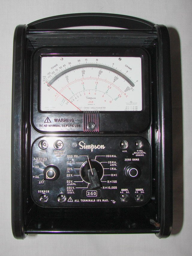
Across nine series the 260’s external shell went from a plain bakelite back with a leather handle and silk-screened face (the original, late 1930s) to a molded, engraved bakelite case with the “Adjust-A-View” tilt handle (Series 2A on) to today’s mirrored, taut-band, PCB-based instrument — and at several points along the way Simpson also offered a fitted roll-top carrying case with a sliding/rolling cover, a case style that goes back to the original 260 and persists today as the 260-8RT / 260-8PRT variants. Vol 2 §5 covers the full case-variant history including the roll-top and the military AFP-1 (a 260-5P variant, Federal Stock Number 6625-985-3951) in detail; the two photos below are a preview.
1.9 What the Simpson 260 is not
It is worth being precise about the 260’s limits, because misapplying it on the wrong node is the most common way a bench tech gets a wrong (or dangerously misleading) reading:
- It is not a DMM. No autoranging, no 0.1%-class accuracy, no digital storage or logging, no true-RMS AC measurement (it is average-responding, calibrated to the RMS of a pure sine — see Vol 3 §4 for why that matters on distorted or non-sinusoidal AC).
- It is not a VTVM. Its 20,000 Ω/V DC input impedance is range-dependent and, on the lower ranges, low enough to load a high-impedance node measurably. A VTVM’s ~10–11 MΩ input is fixed across all ranges and is the right tool for grid, screen, and AVC measurements (see “Bench role,” above, and the B&K 375 / Simpson 311-2 cross-links).
- It is not for measurements above its rating. 1000 V AC/DC circuit-to-ground max on the standard ranges; the 5000 V range exists only via the external HV probe plugged into the dedicated 5000 V jack — it is an accessory, not a switch position (Vol 3 §“the 5000 V range,” Vol 4 §“the 5000 V HV probe”).
- The 10 A range is not fused. The shunt is wired directly to the ±10 A jacks; breaking that lead under load is an arc hazard, covered in full in Vol 4’s safety section and Vol 5’s fuse-service section.
- The range switch is a rotary switch, not a lever. It is worth stating plainly because the phrase “lever-style range switch” circulates in some secondary write-ups of the 260 — every series covered in this dive uses a rotary function/range switch.
Sources
- Simpson Electric — company history (manufacturer, primary): https://simpsonelectric.com/about-us/history/
- Simpson Electric — current 260-8 / 260-8P product page (manufacturer): https://simpsonelectric.com/products/test-equipment/vom-multimeters/260-8-260-8p/
- Simpson 260 Series 8 Instruction Manual (PDF, primary — Table 1-1, sensitivity, ranges, ratings): https://simpsonelectric.com/wp-content/uploads/File/260-8man.pdf
- Simpson 260 Series 8P Instruction Manual (PDF, primary): https://simpsonelectric.com/wp-content/uploads/File/260-8Pman.pdf
- simpson260.com resource hub (per-model pages, photos, manual scans): https://www.simpson260.com/
- radiomuseum.org — original 260 production span (1939–1951): https://www.radiomuseum.org/r/simpson_260_set_tester_2.html