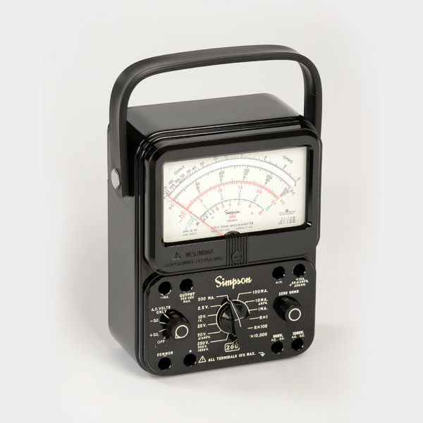
Simpson 260 Series 8 · Volume 2
Simpson 260 — Vol 2: The Series Genealogy (1930s–Today)
Nine numbered series and a half-dozen suffix letters span ninety years — here is exactly what changed, when, and how to tell them apart with the case closed.
2.1 Why the Series Number Matters
Pick up an unmarked 260 at a hamfest and the first question is never “does it work” — it’s “which one is this.” The 260 line ran essentially unbroken from a 1936 patent through a 2026 catalog page, and Simpson kept the exterior silhouette close enough between generations that a fast glance won’t separate a mid-1960s Series 4 from a mid-1970s Series 6. But the insides moved a great deal: the meter suspension changed once, the overload protection scheme was bolted on and then layered three separate ways, the battery complement changed twice, and the jacks changed three times. None of that is cosmetic — it determines what you can safely do with the meter, what parts it needs, and what its accuracy claims actually mean.
This volume is the reference for that question. §3 gives the master comparison table — every series, its approximate years, and its headline changes, in one place. §4 walks each series in its own subsection with a photo and an at-a-glance table. §5 and §6 pull the two threads that keep getting tangled in secondhand write-ups — the movement (pivot-and-jewel → taut-band, and separately, when the mirror arrived) and the “P” suffix (overload protection, which is not one feature but three layered over three decades). §7 covers the physical case variants including the roll-top carrying case. §8 covers the one confirmed military variant. §9 is a field identification guide for an unmarked or partially-marked unit. §10 rounds up leads, the Add-A-Tester lock, and the HV probe; §11 lines up list prices across the decades. §12 closes with what Simpson Electric still sells today.
Two housekeeping notes before the walk starts. First, dates below are approximate on purpose. Simpson did not publish clean model-year introduction dates the way an automaker does; what survives is a mix of manual print dates, dated schematics, price-list snapshots, and radiomuseum.org’s collector-compiled production spans. Where two good sources disagree, both are recorded rather than picking a winner. Second, Simpson did not print a series number on the meter face until the “Series 2A.” The original 260 carries no series marking at all — collectors call it “Series 1” retroactively, and this volume follows that convention but flags it explicitly the one time it matters (§9, tell #1).
Note — Every dated claim in this volume traces back to a specific manual print date, a radiomuseum production-span entry, or a dated schematic — not to a marketing blurb. Where the record is genuinely thin, it says so instead of inventing a crisp year.
2.2 Origins: Ray Simpson and the First 260 (1936)
Simpson Electric Company was chartered in 1936. Its founder, Ray Simpson, had already built the indicating mechanism for the earth-inductor compass carried on Charles Lindbergh’s 1927 transatlantic flight, and is credited with the first commercially practical core meter movement — the D’Arsonval moving-coil design that every 260 in this volume still uses in some form (see Vol 3 §1 for the movement theory).
The Model 260 was Simpson’s first compact “all-purpose” volt-ohm-milliammeter. Simpson’s own company history states it is the VOM “that thousands of military personnel used during World War II” — that is the manufacturer’s own framing, and it is the honest basis for the 260’s reputation as the canonical American field VOM. It is worth being precise about what is and is not documented here: the generic claim of heavy WWII-era military and field-service use is manufacturer-confirmed. The specific claims — repeated all over forums and eBay listings — that the 260 was “the official U.S. Navy standard” or “the Bell System standard” meter did not turn up in any primary source during this research. They are plausible (a compact, rugged, high-sensitivity VOM would have been an obvious institutional pick), but plausible is not the same as confirmed, and this volume will not name a specific institution as “the” standard without a source that actually says so.
Patent 2,051,399 is silk-screened above the ohms scale on the original meter face, with a patent date of August 18, 1936 — visible on surviving units and widely photographed by collectors. That patent date is where the popular “1936” birth year comes from, and it is a legitimate design/patent date. It is not a shipping date, and the two get conflated constantly. The earliest dated paperwork located for this research is a set of operating instructions dated July 20, 1939, with a companion schematic scan dated 1940; radiomuseum.org independently lists the original 260’s production span as “1939–1951.” The best-supported synthesis, and the one used throughout this volume: 1936 is the design/patent year; ~1939 is the first-documented-shipping year; the original body style stayed in the catalog into the 1946–1951 window depending on the source.
One sibling worth naming: simpson260.com notes the Model 215 is “very close in appearance and function” to the 260 — evidently a related set-tester from the same era. A fuller pre-260 lineage (what, if anything, came before the 215) was not found in the sources used here.
2.2.1 Original-260 physical baseline
Everything downstream in this volume is a departure from this starting point, so it is worth listing in full:
Table 1 — full
| Feature | Original 260 |
|---|---|
| Case | ~6½ × 5½ × 3 in, ~3 lb; plain bakelite back |
| Handle | Leather |
| Front labeling | Silk-screened (not engraved) |
| Construction | Extensive hand-wiring; no PCB, no fuses, no calibration trimpots |
| Leads/jacks | Four recessed pin-type jacks (Simpson part 0-008375) |
| Switching | 12-position range switch; separate AC-DC-Output selector; ohms-zero knob |
| Movement | Pivot-and-jewel D’Arsonval — no taut band, no mirror |
| Batteries | Two 3 V cells (Burgess 422 / Eveready 750) + one 1½ V “C” cell, all soldered in |
| Series marking | None — “Series 1” is a collector label, not a factory one |
| Price | $38.95 (1946) |
The soldered-in, oddball-voltage batteries are the origin of the persistent “old 260s need weird batteries” lore that still circulates. It is true of this unit; it stops being true two series later (Series 2A moves to a D cell + four AA cells, and Series 6 lands on the D-cell-plus-9-V combination that persists to the current 260-8 — see §6.5 and the battery table in Vol 5).
2.3 The Master Genealogy Table
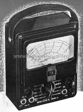
The table below is the backbone of this volume — every numbered series, its best-supported date range, and its headline changes from the prior series. Read it as a summary; §4 unpacks every row.
Table 2 — The Master Genealogy Table
| Series | Approx. years | Key changes from prior series | Movement | Overload protection | Notes |
|---|---|---|---|---|---|
| Original 260 (“Series 1”) | Patent 1936; shipped ~1939; radiomuseum span 1939–1951 (span [uncertain]) | Baseline VOM | Pivot-and-jewel | None | No series marking; leather handle; pin jacks; soldered-in batteries |
| Series 2 / 2A | 1940s–1950s; 1954 price documented; manuals dated 1956 | Engraved black molded case; ohms-zero relocated; “Adjust-A-View” tilt handle | Pivot-and-jewel | None | First to print “Series” on the dial, with 2A. Still pin jacks. D + 4×AA batteries |
| Series 3 / 3A | ~1958–1959 (date-stamped 12 Feb 1959) | Banana-jack leads; printed circuit board introduced; rear adapter lock for Add-A-Tester accessories; batteries reachable from a back cover | Pivot-and-jewel (3A adds self-shielding, spring-loaded jewels) | None | First 260 a modern user “recognizes” |
| Series 4 / 4M | ~1963–1966 | Improved PCB with a calibration (trimpot) circuit | Pivot-and-jewel, self-shielding | None | 4M = first mirrored dial — still pivot-and-jewel, no taut band |
| Series 5 / 5M / 5P | ~1968–1969 | PCB withstands higher voltages | 5 & 5P: pivot-and-jewel. 5M: first taut band + mirror together | 5P = first 260 with overload protection (transistorized relay + reset button) | Two separate firsts land in this series — see §5 and §6 |
| Series 6 / 6M / 6P / 6XL | ~1973 | Taut band now standard; “transit” switch position; combined 1000 V AC/DC jack; +1 V DC jack; 0–10 DC scale; first 3 Amp-Clamp scales; separate battery/fuse door; rubber feet; new D + 9 V battery combo | Taut band standard | Base 6: fuses only. 6P: fuses + resettable relay overload | 6XL = long-lived industrial variant family (manuals into 2001–2005). Jeff owns a 6P |
| Series 7 / 7M / 7P / 7PM / 7PRT | Conflicting: “~1975–1985” (secondary) vs. radiomuseum “1980–2000 ??” [uncertain] | First “OFF/transit” position on the AC/DC switch; reverse-banana safety jacks; “1000 V to ground” printed on face; resized meter window | Taut band (7M mirrored, base 7 non-mirror) | Base 7: fuses. 7P: fused + resettable. 7M: fused + mirror | Best-documented “vintage-modern” 260 in forum/refurb literature; PRT = roll-top |
| Series 8 / 8P / 8Xi / 8XPi / 8RT / 8PRT | ~1990s–present (8Xi manual 1996; 8/8P manuals 2001–2002; current 2026) | Mirror + taut band both standard → drops the “M” suffix; self-shielding taut-band movement; large tri-colored mirrored dial; new 0-25 V range | Taut band standard | Base 8: diode-network movement protection. 8P: diodes + fuses + resettable relay + reset button + audible continuity buzzer | Jeff owns a Series 8. 8RT/8PRT = roll-top |
| Series 9 / 9S / 9SP | ~2006–present | Safety-rated redesign: EN 61010-1, 600 V CAT III; lighter (~2.5 lb vs. 3 lb) | Taut band | 9S base; 9SP = current top protected model | Modern industrial-safety flagship |
Note — “Best-supported” does not mean “certain.” Series 7’s production window is the single messiest date range in the whole line — one secondary source and radiomuseum’s own collector-compiled span disagree by roughly a decade. Both figures are carried forward rather than silently resolved.
2.4 Series-by-Series Walk
2.4.1 The Original 260 (“Series 1”)
Covered in full in §2 above — the baseline against which every later change in this volume is measured. No series number, pivot-and-jewel movement, no mirror, no fuses, no trimpots, pin-type jacks, and a soldered-in three-battery power supply. The original stayed catalog-current, per radiomuseum, into the early 1950s even as later bodies were already displacing it in the field.
Table 3 — The Original 260 ("Series 1")
| Field | Value |
|---|---|
| Approx. years | Patent 1936 · shipped ~1939 · catalog span to ~1946–1951 [span uncertain] |
| Series marking | None (retroactive collector label) |
| Movement | Pivot-and-jewel D’Arsonval |
| Overload protection | None |
| Jacks | Pin-type, 4 recessed |
| Case / handle | Bakelite back, leather handle, silk-screened face |
| Battery | 2×3 V (soldered) + 1×1.5 V “C” (soldered) |
2.4.2 Series 2 / 2A
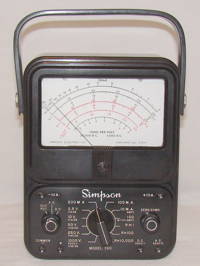
Series 2A is the pivot point where the 260 gets the look most people picture today: a molded black case with engraved (not silk-screened) lettering, and the “Adjust-A-View” tilt handle that props the meter up for reading and stays on the meter line through the current 260-8/260-9. The ohms-zero control moved to the right side of the panel. Documented pricing puts a 260-2 at $36.00 in 1954; manual scans are dated 1956, consistent with a 1950s production window opening sometime in the 1940s.
The genuinely load-bearing fact about this series: the word “Series” appears on the dial for the first time with the 260 Series 2A. Everything before it — including the entire original run — is unmarked. Leads are still pin-type at this point; banana jacks are a Series 3 development. Battery complement moved to one D cell plus four AA cells, retiring the original’s soldered oddball pack.
Table 4 — Series 2 / 2A
| Field | Value |
|---|---|
| Approx. years | 1940s–1950s (1954 price documented; 1956 manual) |
| Series marking | First appears here, on the 2A |
| Movement | Pivot-and-jewel |
| Overload protection | None (“no fuses or trimpots”) |
| Jacks | Still pin-type |
| Case / handle | Molded black case, engraved lettering, Adjust-A-View tilt handle introduced |
| Battery | 1×D + 4×AA |
2.4.3 Series 3 / 3A
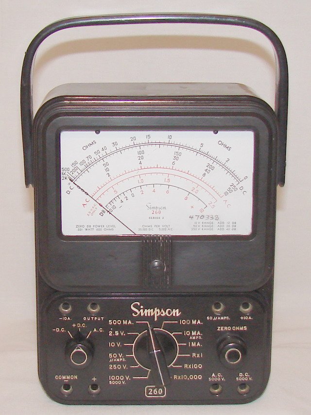
Series 3 is the first 260 a modern bench tech will recognize on sight, and it lands three real firsts at once: banana-jack test leads replace the pin-type jacks, a printed circuit board replaces the original’s hand-wiring for the first time, and a rear “adapter lock” appears for Simpson’s Add-A-Tester accessory line. Batteries also become serviceable from a back cover rather than requiring a full teardown. The 3A variant adds a self-shielding movement with spring-loaded jewels — still pivot-and-jewel, but more shock-tolerant than the plain pivot bearing of 1/2/2A.
Dating is unusually solid here: an internal component carries a date stamp of 12 February 1959, bracketed by manuals dated 1958 and 1959 and a sales brochure from 1955 (evidently covering the pre-3/3A transition period). Best synthesis: ~1958–1959 for the Series 3/3A launch.
Table 5 — Series 3 / 3A
| Field | Value |
|---|---|
| Approx. years | ~1958–1959 (internal date stamp 12 Feb 1959) |
| Movement | Pivot-and-jewel (3A: self-shielding, spring-loaded jewels) |
| Overload protection | None |
| Jacks | Banana jacks — first appearance |
| Case / handle | Same face style as 2A; rear adapter lock added |
| Construction | First printed circuit board |
| Battery | 1×D + 4×AA |
2.4.4 Series 4 / 4M
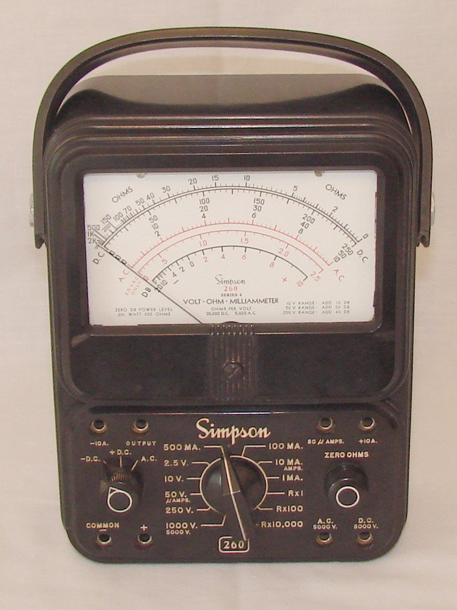
Series 4’s headline circuit change is an improved PCB carrying a calibration circuit — the first factory trimpots in the line, letting a tech dial in accuracy without hand-selecting resistors. The base movement is unchanged from the 3A: pivot-and-jewel, self-shielding, spring-loaded jewels.
The 4M is the one trap in the whole genealogy that gets mangled most often: it introduces the mirrored dial — the first 260 with a mirror behind the scale to kill parallax error — but it is still a pivot-and-jewel movement. No taut band. Mirror and taut-band suspension are two separate upgrades that landed one series apart, and the 4M is squarely on the “mirror yes, taut band no” side of that line (see §5 for the full thread). Manuals for the 4/4M are dated 1963 and 1964; a 1966 price listing ($48.95) brackets the run on the late side.
Table 6 — Series 4 / 4M
| Field | Value |
|---|---|
| Approx. years | ~1963–1966 |
| Movement | Pivot-and-jewel, self-shielding — 4M adds mirror, NOT taut band |
| Overload protection | None |
| Circuit | First PCB with a calibration (trimpot) circuit |
| Case / handle | Unchanged from 3A |
| Battery | 1×D + 4×AA |
2.4.5 Series 5 / 5M / 5P
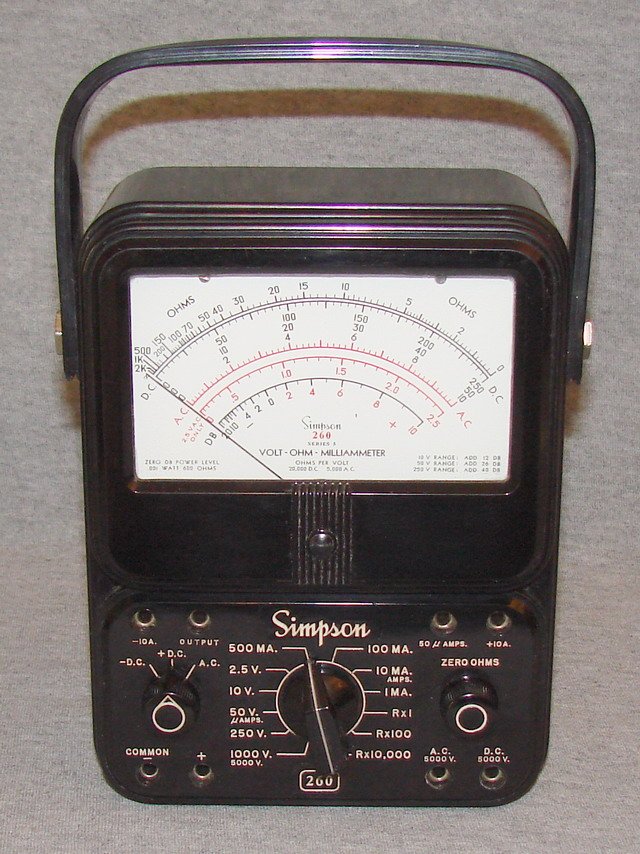
Series 5 is where the genealogy forks hardest, because two unrelated firsts land in the same series number within about a year of each other, on two different suffix variants:
- The 5M (~1969) is the first 260 with taut-band suspension — the mirror it inherits from the 4M is now paired, for the first time, with a taut-band movement rather than a pivot-and-jewel one.
- The 5P (1968) is the first 260 with any overload protection at all: a transistorized relay circuit with a reset button on the left side of the panel. Simpson never published this board’s parts list, and collector documentation (credited to Fred Scoles on simpson260.com) notes production-run variation — some boards used one transistor, some two, with differing resistor counts. The mechanism (“transistorized relay + reset button”) is solid; the exact component-level schematic for the 5P board is not.
The base 5 (no suffix) stays pivot-and-jewel with no overload protection — it is essentially a Series 4 with an uprated PCB that “withstands higher voltages.” Dating across the sub-variants is unusually consistent for this era of the line: radiomuseum lists the base 5 as 1968/69, the 5M as 1969, and the 5P as 1968; the 5P manual itself is dated 1968 and the 5/5M manual 1969. A 1966/1968-era 5P price around $79.95 is documented.
Table 7 — Series 5 / 5M / 5P
| Field | Value |
|---|---|
| Approx. years | ~1968–1969 (5P manual 1968; 5/5M manual 1969) |
| Movement | 5, 5P: pivot-and-jewel. 5M: first taut band (+ mirror) |
| Overload protection | 5P: first ever — transistorized relay + left-side reset button. 5, 5M: none |
| Case / handle | Unchanged silhouette |
| Battery | Low-ohms 1×D cell; high-ohms battery moving toward a ~6 V pack (4×AA-equivalent) — [uncertain] whether that pack was the original holder or a later collector workaround |
2.4.6 Series 6 / 6M / 6P / 6XL
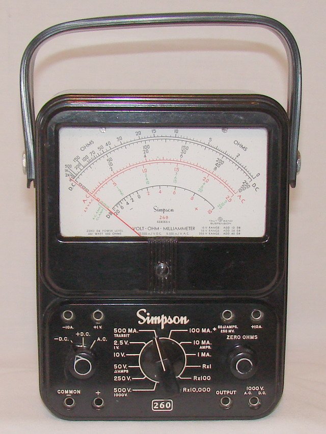
Series 6 (~1973) is the series where the modern 260 stops being a moving target: taut-band suspension becomes the standard movement on the base model rather than an “M” option, and a cluster of other changes lands at once — a “transit” position on the function switch (parks the movement safely for transport), a combined 1000 V AC/DC jack, a new +1 V DC jack, a 0–10 DC scale, the first three Amp-Clamp scales on the dial, a separate small battery/fuse door (no more full-back removal to change a battery), rubber corner feet replacing the earlier raised bumps, and — critically for anyone servicing an old 260 today — a new battery combination: a NEDA 13F “D” cell plus a NEDA 1604A 9 V battery, replacing the 4×AA high-ohms pack used through Series 5. That D-cell-plus-9-V combination is what every later series, including the current 260-8, still uses (Vol 5 covers battery service in depth).
The base 260-6 already carries fuses — a 1 A fuse behind the new battery/fuse door and a 2 A fuse behind the back cover. The 6P adds a resettable electronic overload circuit on top of those fuses, with its reset button positioned just left of the Simpson logo — a different location from the 5P’s left-side button, and the position that stuck for the rest of the line (see §6). Radiomuseum dates both the base 6 and the 6P to 1973; manual scans run 1973/1977/1978, and the long-lived 6XL industrial variant family has manual scans as late as 2001–2005, meaning some Series 6 hardware was still shipping new well into the 2000s even after Series 7 and 8 had launched.
Jeff owns a 260-6P — see the dedicated case-study subsection at the end of §6, and Vol 5 for the battery-holder repair he performed on this exact unit.
Table 8 — Series 6 / 6M / 6P / 6XL
| Field | Value |
|---|---|
| Approx. years | ~1973 launch; 6XL manuals persist to 2001–2005 |
| Movement | Taut band — now standard on the base model |
| Overload protection | Base 6: fuses only. 6P: fuses + resettable relay overload, front reset button |
| Jacks | Combined 1000 V AC/DC jack; new +1 V DC jack |
| Case / handle | Separate battery/fuse door; rubber feet (first) |
| Dial | First 3 Amp-Clamp scales; 0–10 DC scale added |
| Battery | New: NEDA 13F (1.5 V D) + NEDA 1604A (9 V) |
2.4.7 Series 7 / 7M / 7P / 7PM / 7PRT
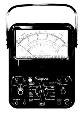
Series 7’s exterior changes are smaller than Series 6’s but touch things a bench user notices daily: the AC/DC selector gets a genuine “OFF/transit” position for the first time (Series 6 only had “transit,” reached from a live range), the pin-and-banana jacks are replaced with reverse-banana safety jacks, “1000 V to ground” is printed directly on the face as a safety reminder, and the meter window is resized. The output jack is explicitly labeled “350 VDC max” on this series’ face — a spec that had been true of earlier series too but is now called out on the panel itself.
Overload protection follows the pattern set by Series 6: base 7 gets fuses, 7P adds a fused + push-button-reset overload circuit, and 7M adds the mirror to a fused-but-unprotected base 7. The 7PM and 7PRT suffixes stack a mirror or roll-top case onto the protected 7P.
Dating this series is the messiest date question in the entire genealogy. One secondary source (irationaudio.com, which documents a real 7P/7M teardown) places the run at roughly 1975–1985; radiomuseum’s own collector-compiled span for the base Series 7 is “1980–2000 ??” — a decade later and twice as long, with radiomuseum’s own question marks attached. The 7/7M manual on file is dated 1981; 7P manuals run 1982 and 1986. Those manual dates sit comfortably inside both proposed windows, so they don’t resolve the disagreement. This volume records both spans rather than picking one: treat Series 7 production as somewhere in the late 1970s through the 1980s, possibly extending toward 2000 for late 7XL-style variants, and do not cite a single crisp year for it.
Table 9 — Series 7 / 7M / 7P / 7PM / 7PRT
| Field | Value |
|---|---|
| Approx. years | Disputed: ~1975–1985 (secondary) vs. radiomuseum “1980–2000 ??” |
| Movement | Taut band (7M mirrored; base 7 non-mirror) |
| Overload protection | Base 7: fuses. 7P: fused + push-button-reset relay overload. 7M: fused + mirror |
| Jacks | Reverse-banana safety jacks — first appearance |
| Panel | New “OFF/transit” position; “1000 V to ground” printed on face; resized meter window |
| Case | PRT = roll-top variant |
2.4.8 Series 8 / 8P / 8Xi / 8XPi / 8RT / 8PRT
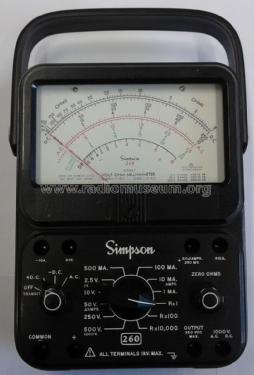
This is Jeff’s own series, and the one where the two long evolution threads in §5 (movement) and §6 (overload protection) both reach their modern, layered state. The base 260-8 makes both the taut-band movement and the mirrored dial standard equipment — for the first time in the line’s history neither feature is an “M” option, which is exactly why Series 8 has no “M” suffix: there is nothing left for an “M” to add. The dial itself grows into a large tri-colored mirrored scale, and a new 0-25 V AC/DC range joins the traditional ladder (Series 8’s own instruction manual lists this as one of two headline “New Features,” alongside the mirror).
Overload handling on the base 8 is a diode network across the movement — a passive clamp, not a relay, protecting the coil from transient overloads without any user-visible reset action. The 8P layers three more protection mechanisms on top of that same diode network: a resettable electronic relay that senses the voltage drop across the movement via a polarity-independent bridge network and trips at roughly 3× rated full scale, the same two fuses used on the base 8 (F1 1 A/250 V, F2 2 A/600 V — see Vol 5 §7 for exact part numbers), a front-panel reset button that pops up about 3∕16 in when tripped, and an audible continuity buzzer that is not covered by the electronic protection. Some ranges — 1 V, 10 A, 50 µA, 250 mV, and 500/1000 V AC and DC — sit outside the electronic relay’s coverage. Most of those fall back to the fuses and diode network; the 10 A range is the odd one out — its shunt wires straight to the ±10 A jacks with no fuse in circuit at all, so it relies on the diode network alone (never break a lead on the 10 A range while energized — the arc hazard is real with no fuse to interrupt it). This is documented in Vol 3 §7 and Vol 4’s safety section.
Dating the launch is inferential rather than documented: the earliest dated manual located is for the 8Xi variant, 1996; base 8/8P manuals on file run 2001–2002. The best-supported (but not confirmed) launch estimate is the mid-1990s. What is not in question is current status: the 260-8 and 260-8P are still in Simpson Electric’s active catalog in 2026 (§12), making this the longest-lived single body style in the 260’s history by a wide margin.
Variants worth knowing: 8Xi/8XPi carry electronics-industry-oriented feature sets; 8RT/8PRT ship the meter in the roll-top carrying case (§7.3). 2007-era pricing put the base 8 around $208 and the 8P around $278.
Table 10 — Series 8 / 8P / 8Xi / 8XPi / 8RT / 8PRT
| Field | Value |
|---|---|
| Approx. years | ~1990s (LIKELY, not confirmed) – present (CONFIRMED current 2026) |
| Movement | Taut band + mirror both standard — no “M” suffix needed |
| Overload protection | Base 8: diode network (passive). 8P: diodes + 2 fuses + resettable relay (~3× FS trip) + front reset button + audible continuity buzzer |
| New range | 0-25 V AC/DC |
| Dial | Large tri-colored mirrored scale |
| Battery | NEDA 13F (D) + NEDA 1604A (9 V) — 9 V also feeds the 8P’s relay |
2.4.9 Series 9 / 9S / 9SP
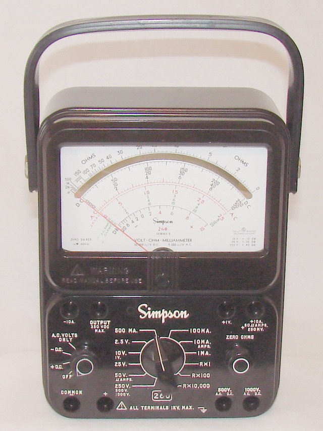
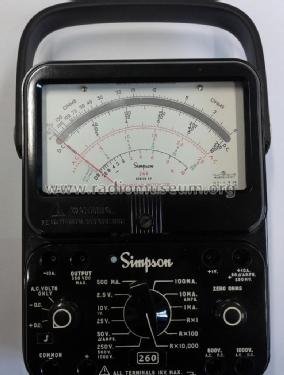
Series 9 (~2006–present) is a safety-driven redesign rather than a circuit-driven one: it meets EN 61010-1, 600 V CAT III — a modern electrical-safety standard that the earlier series, designed decades before it existed, were never rated against. The physical unit is also lighter, at roughly 2.5 lb versus the Series 8’s 3 lb. The movement remains taut-band; detailed movement specifics beyond “analog VOM, taut band” were not found for this series in the sources used here.
The suffix pattern from Series 5 onward continues: 9S is the base current model and 9SP is the protected variant, with simpson260.com stating overload protection “will be offered on all series models after [5P], up to and including the current Series 9” — i.e., the 9SP is not a one-off, it is the latest link in the same protection lineage that started with the 5P (§6). Manual dates on file run 2006/2007; a 2017 price listing puts a 260-9 around $525, reflecting both inflation and the added safety-rating engineering.
Table 11 — Series 9 / 9S / 9SP
| Field | Value |
|---|---|
| Approx. years | ~2006–present |
| Movement | Taut band |
| Overload protection | 9S: base. 9SP: current top protected model in the line |
| Safety rating | EN 61010-1, 600 V CAT III — first 260 series to carry a modern safety-standard rating |
| Weight | ~2.5 lb (down from 3 lb on Series 8) |
2.5 The Movement Thread: Pivot-and-Jewel to Taut Band
This is the single most-mangled fact about the 260 line, worth pulling out of the series walk and stating on its own so it cannot be misquoted:
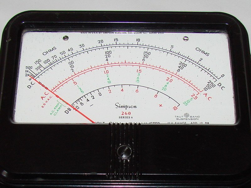
Taut-band suspension was NOT introduced on Series 8. Taut band first appears on the Series 5M (~1969), offered as an upgrade over the base pivot-and-jewel 5 and 5M’s sibling 5P. It becomes standard equipment on the base model starting with Series 6 (~1973). By the time Series 8 arrives (~1990s), taut band has already been the default movement for roughly two decades — Series 8’s real contribution is making the mirror standard alongside an already-standard taut band, and dropping the “M” suffix because there is no longer a non-mirrored, non-taut-band base model left to distinguish it from.
Unpacked chronologically:
Table 12 — Unpacked chronologically
| Era | Movement | Mirror |
|---|---|---|
| Original 260 through Series 3A | Pivot-and-jewel (3A: self-shielding, spring-loaded jewels) | None |
| Series 4 (base) | Pivot-and-jewel | None |
| Series 4M | Pivot-and-jewel — still no taut band | First mirror |
| Series 5, 5P | Pivot-and-jewel | None |
| Series 5M (~1969) | First taut band (paired with the mirror inherited from 4M) | Mirror |
| Series 6 (~1973) | Taut band — now standard on the base model | Still an “M” option through Series 7 |
| Series 7 (base) | Taut band | None |
| Series 7M | Taut band | Mirror |
| Series 8 (~1990s) | Taut band (standard, unchanged from Series 6) | Mirror now also standard → “M” suffix dropped |
| Series 9 | Taut band | Mirror (standard, continuing 8’s pattern) |
Two separate features, two separate introduction points, one series apart: mirror = Series 4M (~1963–66); taut band = Series 5M (~1969), standard from Series 6 (~1973). The 4M is the specific trap — it has the reflective dial an eye immediately associates with a “premium” later meter, but its needle still rides on jeweled pivot bearings, not a taut suspension ribbon. An author, reviewer, or eBay description that calls out a 4M’s mirror as proof of a taut-band movement is making exactly the error this section exists to prevent.
Mechanically, the shift matters beyond nomenclature. Pivot-and-jewel bearings are a miniature jeweled pivot resting in a cup — precise, but subject to wear, shock damage, and drift over decades of use and storage. A taut-band suspension instead hangs the moving coil from a pre-tensioned metal ribbon under slight torsional twist — no bearing to wear, and dramatically better shock tolerance, at the cost of a more delicate initial calibration (over-torquing or shock-loading a taut band can shift its zero point rather than merely wearing a bearing). Vol 5 §3 covers what this means for refurbishing an older pivot-and-jewel unit versus a taut-band Series 6-and-later unit.
2.6 The “P” Suffix: Overload Protection Across Three Decades
“P” means overload protection on every series it appears on — that part is simple and confirmed across every source used for this volume. What is not simple, and what a shorthand “the P models have a fuse” description gets wrong, is that the protection is layered, and the layering changed generation to generation. No 260-P is “just a fuse” model; by Series 8P there are four distinct protection mechanisms stacked on one unit.
2.6.1 First appearance: the 5P (1968)
The 260-5P is the first 260 with any overload protection at all — a transistorized relay circuit with an overload reset button on the left side of the panel. Simpson never published this circuit’s parts list or a clean schematic; collector documentation (credited to Fred Scoles on simpson260.com) records real production-run variation, with some boards built around one transistor and others around two, and differing resistor counts between runs. The mechanism — “transistorized relay trips on overload, reset button restores it” — is solid and confirmed. The exact component values are not, and this volume does not invent them.
2.6.2 Series 6P: fuses plus a resettable relay
The base 260-6 already carries fuses on its own — a 1 A fuse behind the newly separate battery/fuse door, plus a 2 A fuse behind the main back cover. The 6P adds the resettable electronic overload circuit on top of those fuses, with its reset button relocated to just left of the Simpson logo — the position every later P-series settles on. This is the layering point worth internalizing: from Series 6 onward, “P” does not mean “this model has protection and the base model doesn’t” — the base model already has fuses. “P” specifically means “plus a resettable electronic relay and a front reset button,” added on top of a fusing scheme every same-series unit shares.
2.6.3 Series 7P and 7M
Series 7 continues the pattern: base 7 is fused, 7P is fused plus a push-button-reset overload relay, and 7M is fused plus the mirror (mirror and electronic protection are independent options at this point — a unit can be 7M without being 7P, or vice versa).
2.6.4 Series 8P: the fullest stack in the line
The base 260-8 uses a diode network across the movement to shunt overload current around the coil — a passive, always-on clamp with no moving parts and nothing to reset. The 8P adds three more layers on top of that same diode network:
- Two fuses — F1 (1 A/250 V, 3AG, Littelfuse 312001) and F2 (2 A/600 V, Littelfuse BLS or Bussmann BBS) — the same part numbers used on the base 8. Full detail in Vol 5 §7.
- A resettable relay, sensing the voltage drop across the movement through a polarity-independent bridge network so the protection works regardless of which way current flows, tripping at approximately 3× the range’s rated full scale. Relay contacts sit in the −COMMON line and latch open until the front-panel reset button is pressed; on a hard overload the button visibly pops up roughly 3∕16 in above the panel.
- An audible continuity buzzer — useful for quick go/no-go continuity checks without watching the needle, but explicitly not covered by the electronic overload protection; it can still be damaged by an overload the relay doesn’t catch on its range.
Some ranges fall outside the relay’s coverage regardless of series: on the 8P specifically, 1 V, 10 A, 50 µA, 250 mV, and the 500 V/1000 V AC and DC ranges get no relay backstop. Most of those still have the fuses and diode network behind them — but the 10 A range has no fuse in the circuit at all (the shunt wires straight to the ±10 A jacks), so on that one range the diode network is the only protection there is, fuses included. This is documented in the manual’s own protection-exclusion list and repeated in Vol 3 §7 and Vol 4’s safety section — do not assume every range on a “protected” P model is actually relay-protected, and do not assume every excluded range is at least fuse-protected.
One-line summary for an author, reviewer, or bench tech: the P protection is layered, not singular — fuses (crude, from Series 6 on), a diode/clamp network protecting the movement itself (from Series 8 on), and a resettable relay/transistor cutout with a front reset button (the actual feature the “P” names, from the 5P on). Never describe P-model protection as “just a fuse.”
2.6.5 Characterizing Jeff’s 260-6P
Jeff’s own 6P sits at the middle layer of this progression — past the 5P’s first-generation transistor relay, but one generation before the 8P’s diode-network-plus-buzzer stack. Specifics for this unit:
Table 13 — relay, but one generation before the 8P's diode-network-plus-buzzer stack. Specifics for this unit
| Field | Value |
|---|---|
| Vintage | ~1973 (radiomuseum “1973 ?”; 6P manual dated 1973) |
| Case | Bakelite, 5¼ × 7 × 3⅛ in |
| Movement | Taut band suspension (standard by Series 6) |
| Overload protection | Fuses + resettable relay, front reset button left of the Simpson logo |
| Battery/fuse access | Separate battery/fuse cover door |
| Rated circuit-to-ground | 1000 V AC/DC |
| Rear accessory port | Adapter lock, for Add-A-Tester accessories |
| Batteries | NEDA 13F “D” cell (R×1/R×100) + NEDA 1604A 9 V (R×10,000 and the overload relay) |
| Series-6 firsts present | ”Transit” switch position; three Amp-Clamp scales |
A dedicated “260-6P Theory of Operation” document exists on simpson260.com — confirmed as existing and the primary refurb reference for this exact model; Vol 5’s battery-holder repair case study (Jeff’s actual work on this unit) draws on the same general design this document covers.
2.7 Case and Body Variants
2.7.1 From leather-and-bakelite to molded-and-engraved
The exterior evolution runs in one direction across the whole line: the original 260 has a plain bakelite back, a leather handle, and a silk-screened face — no engraving, nothing molded-in. Series 2A introduces the molded black bakelite case with engraved lettering and the “Adjust-A-View” tilt handle that survives, essentially unchanged in concept, all the way to the current 260-8 and 260-9. Every series from 2A forward keeps that molded-bakelite body language; later production is sometimes described as bakelite/molded plastic without a documented material change. One frequently repeated claim — “old ones are bakelite, new ones are ABS” — turns up on collector forums but was not found stated explicitly by Simpson in any source used here. Treat it as plausible, unconfirmed shop lore, not a documented fact.
2.7.2 Red vs. black — not a series discriminator
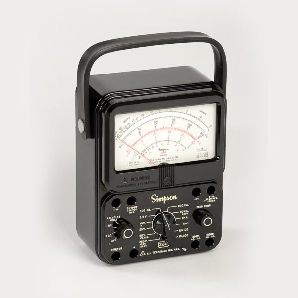
Simpson’s current product photography for the 260-8/260-8P shows a red-cased unit, and the image
filename on Simpson’s own site literally contains “260-8-R.” Every classic vintage unit covered in §4,
by contrast, is black bakelite. It would be easy to read that as a rule — “red means modern, black
means vintage” — but no formal red-vs-black series rule was found in any source used here. The color
appears to be a cosmetic/marketing option available on current-production units, not a discriminator
that tells you anything about which series, sub-variant, or protection level you’re holding. Do not
assert a red-vs-black meaning beyond “red is a modern cosmetic option Simpson currently offers.” Note
specifically: the current 260-8 shown in this volume’s own reference photo (series8_current.jpg) is
black — Simpson sells both colorways today, so “current” and “red” are not synonymous either.
2.7.3 The Roll-Top case
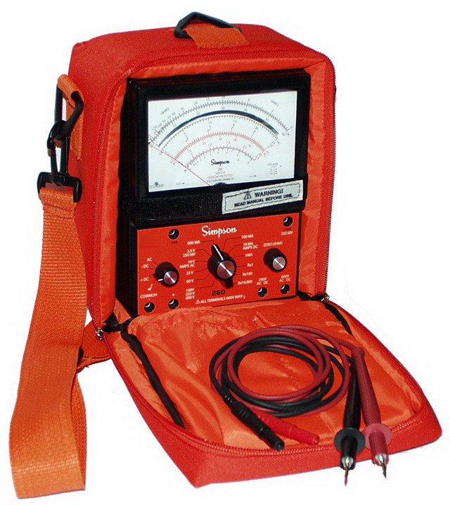
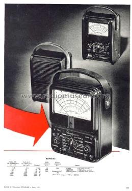
A distinct carrying-case variant runs alongside the standard handle-and-tilt body: the roll-top (“RT”) case — a fitted carrying case with a sliding/rolling cover, roughly 9 × 6½ × 4½ in and ~5½ lb (considerably bulkier than the bare meter). Fuses on a roll-top unit are reached “under the silver plate which rotates to allow removal,” per simpson260.com’s description, and the 8RT carries an “Off” switch position where its companion 8PRT instead places the continuity buzzer control.
Roll-top variants are documented on 260-7PRT, 260-8RT, and 260-8PRT — but the concept itself is much older than Series 7/8: radiomuseum hosts photos of an early original 260 already housed in a roll-top case (“set_tester_260_roll_top_case”), meaning Simpson offered a roll-top carrying option from close to the very beginning of the line, not as a late-production novelty. Do not describe the roll-top as a “Series 8 feature” — it is a case option that recurs across the line’s entire history.
2.7.4 The separate battery/fuse door as a physical-generation tell
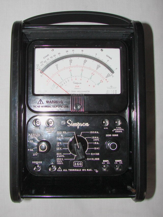
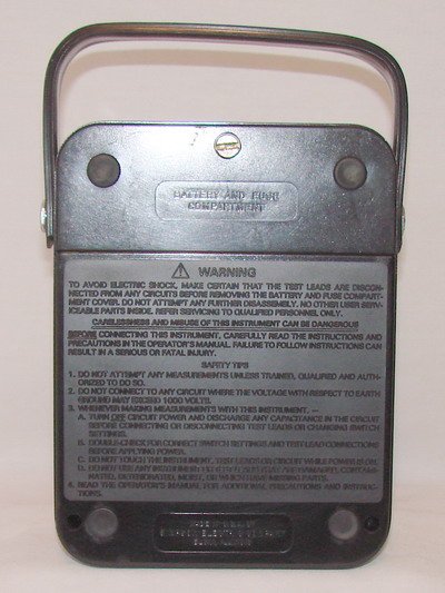
One case change doubles as a fast identification tell (reused in §9): starting with Series 6, the battery and fuse compartment gets its own small door, separate from the main back cover, closed with a single captivated screw. Earlier series (5 and before) require removing the entire back cover to change a battery.
2.8 Military and Special Versions
The one confirmed military variant in the sources used for this volume is the AFP-1, the U.S. military version of the 260-5P, carrying Federal Stock Number 6625-985-3951. It is distinguished physically by rubber feet screwed onto the corner bumps (a modification of the standard 5-series raised-bump case, predating the Series 6 body that made rubber feet standard equipment) and was powered by a D cell plus an Eveready 417 15 V battery for its ohms high range — a genuinely different battery spec from the civilian 5P’s contemporaneous pack, and a reminder that “15 V” battery claims found elsewhere online (see Vol 5’s battery table) are not universally wrong, just wrong for the civilian line. AFP-1 manuals on file are dated 1966 and 1969, with a separate overload-test document.
Two Simpson military calibration bulletins are confirmed to exist — TB 9-6625-2352-35 (covering the 260 up through Series 5) and TB 9-6625-2354-35 (covering Series 6–8) — independent evidence of sustained military service and support well past the WWII era referenced in §2.
One claim this volume deliberately does not make: a specific “TS-###” JAN/AN military type number for the 260. That numbering convention shows up for plenty of other WWII/Cold-War-era military test gear, and it is tempting to assume the 260 carries one too — but no TS-number was found for it in any source used here. The 260’s documented military identity is the AFP-1 designation plus FSN 6625-985-3951, not a TS-number. Do not assert one.
A few other lettered designations — “SR” and the AFP-1 itself — appear as distinct model pages on simpson260.com; full specifics for the SR variant were not captured in this research pass.
Note — For the broader WWII-military-use claim covered in §2 (thousands of military personnel trained on the 260), the manufacturer’s own history page is the source, and it does not name a specific service branch or program by name beyond “military personnel.” Treat any “Navy standard” or “Bell System standard” claim you encounter elsewhere as unverified marketing shorthand, not documented fact.
2.9 Series-Identification Guide
For an unmarked, partially marked, or suffix-ambiguous unit on the bench, work through these tells in order — fastest and most reliable first:
- Read the dial. From Series 2A onward, the series is normally printed directly on the face (e.g. “260 Series 6P”). The original 260 carries no series marking and instead shows patent 2,051,399 — if you see that patent number and no series text, you likely have the original / a “Series 1” by collector convention.
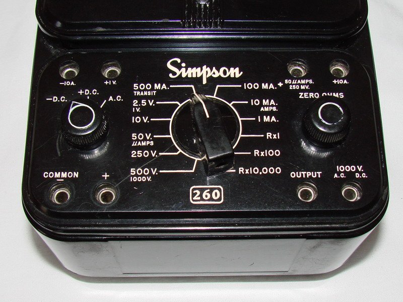
- Check the leads/jacks. Pin-type recessed jacks → original or Series 2 (pre-1959). Banana jacks → Series 3 through Series 6. Reverse-banana safety jacks → Series 7 and later.
- Look at the handle and case. Leather handle + silk-screened face → original. Molded black case + engraved lettering + Adjust-A-View tilt handle → Series 2A onward. Rubber corner feet → Series 6 onward (earlier series have raised corner bumps instead; the military AFP-1 has rubber feet screwed onto those bumps as a field modification of the 5-series body).
- Check the battery/fuse access. A separate small battery/fuse door → Series 6 or later. If the entire back cover has to come off to reach a battery, you’re at Series 5 or earlier (Series 3 onward at least spared you a full teardown, even without the dedicated door).
- Look for a front reset button. A reset button on the front panel, left of the Simpson logo → a “P” model (5P, 6P, 7P, 8P, 9SP). No reset button → non-P. (Note the 5P’s button sits on the left side of the panel rather than next to the logo — see §6.1 — so a 5P can look slightly different from later P-series buttons even though the function is identical.)
- Check for a mirrored dial. Present → 4M, 5M, 6M, or 7M, or any Series 8 or 9 (mirror is standard by then). Absent → a non-M unit from Series 1 through 7.
- Look for a “transit” position. A “transit” position first appears on Series 6; an “OFF/ transit” combined position on the AC/DC switch is a Series 7-and-later tell.
- Date-code the internal potentiometers (Series 3 and later). CTS potentiometers inside carry an EIA
code (137) followed by a year/week stamp — e.g.,
137 72 56reads as CTS, 1972, week 56. Useful for narrowing an exact production year within a series once the series itself is known. This is a forum-sourced but widely repeated convention, not a Simpson-published one. - Use the battery type as a coarse era check. Soldered 3 V cells + a 1.5 V “C” cell → original. D cell + 4×AA → Series 2 through 5. D cell + 9 V (NEDA 1604A) → Series 6 and later. This doubles as a fast sanity check against tell #4 (they should agree).
Applied together, tells 1–5 alone are usually enough to pin an unknown 260 to a specific series or a narrow two-series range; tells 6–9 resolve the remaining ambiguity (M-suffix, exact year, protection level).
2.10 Accessories Across the Line: Leads, the Add-A-Tester Lock, and the HV Probe
The genealogy above is mostly about what changed inside the case. A few accessory-level changes track the same series boundaries and are worth pulling together in one place, because they double as identification tells and as practical parts-sourcing information for a unit on the bench today.
Test leads. The lead style changes track the jack changes in §9 tell #2 almost exactly, because the lead and the jack are obviously matched pairs:
Table 14 — lead and the jack are obviously matched pairs
| Series range | Lead catalog number | Length | Connector style |
|---|---|---|---|
| Original 260 | Recessed pin-type leads, part 0-008375 | — | Pin |
| Series 3–6 | Catalog No. 00125 | 48 in | Banana |
| Early-260 alternate | Catalog No. 02055 + clip set 01927 | 36 in | Pin/early |
| Series 7–9 (current) | Catalog No. 00043 | 48 in | Reverse-banana, combination probe-tip + removable rubber-sleeved alligator clips |
Catalog No. 00043 is the lead set that ships with a new 260-8/8P/9S/9SP today, rated 1000 V AC/DC, 10 A, and it is still stocked by the usual test-equipment distributors — a genuine practical upside of buying into the still-in-production end of this line rather than an early series.
The Add-A-Tester rear lock. Series 3 introduced a rear “adapter lock” for Simpson’s Add-A-Tester accessory line (§4.3, Series 3/3A) — a mechanical mounting point, not an electrical range. It persists on Jeff’s own 6P (§6.5) and on later series, though documentation of exactly which Add-A-Tester modules were sold against it was not captured in the sources used for this volume.
The 5000 V HV probe. Every series in this line from Series 8 backward that documents a “5000 V” jack reaches that range the same way — an external high-voltage probe plugged into the jack, not a switch position (Vol 3 §4 has the multiplier-ladder theory). What is not confirmed is a specific Simpson part number for that probe: a commonly repeated figure of “00033” could not be verified against Simpson’s current accessory documentation during this research and should be treated as unconfirmed rather than cited as fact.
2.11 Pricing Across the Decades
List prices are one of the few genuinely dated data points that survive from Simpson’s own catalogs and price sheets, and lining them up gives a rough sense of how the instrument’s market position moved alongside its feature set:
Table 15 — alongside its feature set
| Year | Series | List price | Notes |
|---|---|---|---|
| 1946 | Original 260 | $38.95 | No fuses, no trimpots, soldered-in batteries |
| 1954 | Series 2 | $36.00 | First series with “Series” printed on the dial (2A) |
| 1966 | Series 4 | $48.95 | First mirrored dial (4M variant) era |
| 1966/1968 | Series 5P | ~$79.95 | First overload-protected 260 |
| 2007 | Series 8 (base) | ~$208 | Current-era diode-network protection |
| 2007 | Series 8P | ~$278 | Full four-layer protection stack |
| 2017 | Series 9 | ~$525 | EN 61010-1 / 600 V CAT III safety redesign |
The price roughly quintuples from the original to a base modern 260-8 across sixty-plus years — well within the range of ordinary inflation plus real feature growth (PCB construction, calibration trimpots, taut-band and mirror, layered overload protection). The jump to the Series 9’s ~$525 reflects the CAT III safety-standard engineering more than any circuit change, which tracks with §4.9’s description of Series 9 as a safety-driven redesign rather than a circuit-driven one.
2.12 Current Status and Production
The 260 is still in production in 2026. Simpson Electric (Lac du Flambeau, WI) currently sells the 260-8 and 260-8P, plus a mining/construction-oriented 260-8MCS variant, and the safety-rated 260-9S / 260-9SP, alongside a “Renew Kit” for servicing the 260-8 series. This is not a nostalgia reissue — it is the same catalog line, continuously updated, that this volume has just walked through generation by generation.
- Direct heir to Jeff’s Series 8: the current 260-8 / 260-8P are, literally, the same catalog line — not a remake or a tribute product.
- Top current model / most heavily protected: the 260-9SP, carrying the EN 61010-1 / 600 V CAT III safety rating covered in §4.9’s Series 9 subsection.
- Everything from the original 260 through Series 7 is discontinued/vintage-only. Series 6XL variants are the one exception with a documented long tail — manual scans persist on paper into the mid-2000s even though the Series 6 body dates to ~1973.
For a unit purchased new today, or a Renew Kit ordered against an existing Series 8, the specifications and refurb guidance in Vol 3 through Vol 5 of this deep dive apply directly — the 260-8/8P design has not meaningfully changed since its documented 1990s-to-2000s manual revisions.
2.13 Cross-References
- Vol 1 covers why an analog VOM like the 260 still earns bench space today, and where it sits relative to a high-impedance VTVM on grid/screen work — see B&K 375 VTVM and Simpson 311-2 VTVM for those alternatives.
- Vol 3 covers the movement, the range-switch and multiplier-ladder circuit theory, and how to read the mirrored/cascaded/reciprocal-ohms scales in detail — the electrical follow-up to this volume’s mechanical/generational one.
- Vol 4 covers safe operating procedure for the ranges and protection schemes described here, including the one-hand rule and 1000 V-to-ground limit referenced in §4 and §6 — see also the shared safety doc _shared/legal_ethics.md.
- Vol 5 puts the movement, protection, and battery threads from this volume to work on Jeff’s actual units — most notably the corroded battery-holder repair he performed on the 6P characterized in §6.5.
- Vol 6 distills this entire genealogy into a single quick-reference identification table for the bench.
Sources
- Simpson Electric — company history (manufacturer): https://simpsonelectric.com/about-us/history/
- Simpson Electric — current 260-8 / 260-8P product page: https://simpsonelectric.com/products/test-equipment/vom-multimeters/260-8-260-8p/
- Simpson Electric — VOM catalog: https://simpsonelectric.com/products/test-equipment/vom-multimeters/
- Simpson Electric — 260-8 image asset: https://simpsonelectric.com/wp-content/uploads/2020/03/260-8-R-600x600.jpg
- simpson260.com — resource hub / index of all model pages: https://www.simpson260.com/
- simpson260.com — original 260: https://www.simpson260.com/260-1/simpson_260-1.htm and https://www.simpson260.com/260-1/simpson_260-1a.htm
- simpson260.com — Series 2: https://www.simpson260.com/260-2/simpson_260-2.htm
- simpson260.com — Series 3: https://www.simpson260.com/260-3/simpson_260-3.htm
- simpson260.com — Series 4 / 4M: https://www.simpson260.com/260-4/simpson_260-4.htm , https://www.simpson260.com/260-4/simpson_260-4m.htm
- simpson260.com — Series 5 / 5M / 5P: https://www.simpson260.com/260-5/simpson_260-5.htm , https://www.simpson260.com/260-5/simpson_260-5m.htm , https://www.simpson260.com/260-5/simpson_260-5p.htm
- simpson260.com — Series 6 / 6P: https://www.simpson260.com/260-6/simpson_260-6.htm , https://www.simpson260.com/260-6/simpson_260-6p.htm
- simpson260.com — Series 7: https://www.simpson260.com/260-7/simpson_260-7.htm
- simpson260.com — Series 8 / 8P / 8RT: https://www.simpson260.com/260-8/simpson_260-8.htm , https://www.simpson260.com/260-8/simpson_260-8p.htm , https://www.simpson260.com/260-8/simpson_260-8rt.htm
- simpson260.com — Series 9S/9SP: https://www.simpson260.com/260-9/simpson_260-9s.htm
- simpson260.com — AFP-1 (military): https://www.simpson260.com/260/simpson_260-afp-1.htm
- simpson260.com — downloads/manuals index: https://www.simpson260.com/downloads/downloads.htm
- radiomuseum.org — original 260 (1939–1951, roll-top photos): https://www.radiomuseum.org/r/simpson_260_set_tester_2.html
- radiomuseum.org — Series 5M (1969), 5P (1968): https://www.radiomuseum.org/r/simpson_volt_ohm_milliammeter_260_series_5m.html , https://www.radiomuseum.org/r/simpson_vom_260_5p.html
- radiomuseum.org — Series 6P (1973): https://www.radiomuseum.org/r/simpson_volt_ohm_milliammeter_260_series_6p.html
- radiomuseum.org — Series 7 (1980–2000?): https://www.radiomuseum.org/r/simpson_vom_260_series_7.html
- radiomuseum.org — Series 7M (1981): https://www.radiomuseum.org/r/simpson_volt_ohm_milliammeter_260_series_7m.html
- radiomuseum.org — Series 8P (~1996; diode + relay protection): https://www.radiomuseum.org/r/simpson_multimeter_260_series_8p.html
- radiomuseum.org — Series 8XPi: https://www.radiomuseum.org/r/simpson_volt_ohm_milliammeter_260_series_8_xpi.html
- The Garage Journal — first-version 260 owner thread (photos, patent): https://www.garagejournal.com/forum/threads/first-version-simpson-260-260-1-vom-multimeter-ca-1936-1946.113360/
- irationaudio.com — 260 Series 7P/7M refurb + dates: https://irationaudio.com/2015/03/30/simpson-260-vom/
- Simpson 260 Series 8 Instruction Manual (primary): https://simpsonelectric.com/wp-content/uploads/File/260-8man.pdf
- Simpson 260 Series 8P Instruction Manual (primary): https://simpsonelectric.com/wp-content/uploads/File/260-8Pman.pdf
- Antique Radio Forums — series-difference/dating threads (corroboration only): https://antiqueradios.com/forums/viewtopic.php?t=108212 , https://antiqueradios.com/forums/viewtopic.php?f=8&t=368988