Simpson 260 Series 8 · Volume 4
Simpson 260 — Vol 4: Using the 260 — Operating Procedure & Safety
How to set up, zero, select, read, and — above all — not destroy either the meter or yourself with a 20,000 Ω/V analog VOM.
4.1 Scope of This Volume
Vol 1 explained why an analog meter still earns bench space; Vol 2 walked the series genealogy; Vol 3 went schematic-deep on the movement, the multiplier ladder, and the ohms circuit. This volume is the one you actually keep open on the bench: the step-by-step operating procedure for every function on a Series 6 through Series 8/8P 260, plus the safety rules that keep the meter — and you — intact.
Everything below is written against Jeff’s own two units, a Series 8 and a Series 6P, but the procedure is essentially unchanged back through Series 3 (banana jacks, PCB) and forward to the current 260-9SP. Where a control or jack is series-specific (the TRANSIT position, the reset button, the combined 1000 V jack), that is called out — see Vol 2 for the full per-series changelog and Vol 6 for the one-page cheatsheet version of everything in this volume.
Note — The 260 is a manually-ranged instrument. There is no auto-range, no continuity beeper on a base (non-P) model, and — critically — the range/function selector is a rotary switch, not a push-button or lever. Every measurement below starts with physically turning a knob to the correct function and range before a lead ever touches a circuit.
4.2 Before You Touch the Leads — Setup and Mechanical Zero
4.2.1 Orientation and handling
The 260’s accuracy specifications (Vol 3 Table 1-1) are stated with the instrument horizontal — that is the position it was calibrated in at the factory. Reading it standing on edge or propped at a steep angle introduces a small gravity-dependent error in the pivot-and-jewel (pre-taut-band) movements especially. The Adjust-A-Vue tilt handle (Series 2A onward) props the meter at a comfortable viewing angle — but tilting it on the bail is itself a departure from the calibrated horizontal position, so treat that tilt as a small tradeoff of viewing comfort against accuracy, not a free lunch: for the most accurate reading, keep the meter horizontal and lean in to read it rather than propping it up.
Before connecting anything:
- Set the meter down horizontal, leads disconnected from any circuit.
- Inspect the leads and jacks — cracked insulation or a loose banana plug is a shock/arc hazard before it’s an accuracy problem. (See §10.)
- If the unit is a P model (5P/6P/7P/8P/9SP), confirm the front-panel reset button is down/flush — a popped-up reset button means the electronic overload circuit tripped on a previous overload and is latched open; nothing will read on the protected ranges until it’s pressed back in (Vol 5 §7 covers diagnosing why it tripped before you just reset and move on).
4.2.2 Mechanical zero — no leads connected
With no leads plugged in and the function/range switch anywhere in the DC volts or DC current position (not OHMS — the ohms function’s internal battery is irrelevant to this step, but starting in a “dead” function avoids any accidental live reading while your hands are near the adjuster):
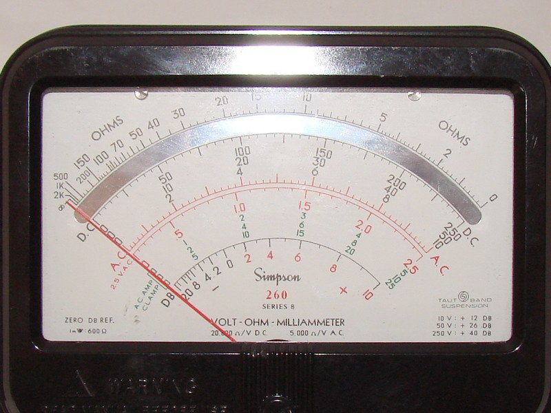
- Look at the pointer. On a mirrored-dial series (4M-on for the M option, standard from Series 8) you should see the pointer’s reflection in the mirror band directly behind the needle — more on why that mirror matters for reading in §2.3 below and in depth in Vol 3 §“Reading the Scales.”
- The pointer should rest exactly on the left-hand zero mark of the DC/AC scale (the mechanical rest position, distinct from the ohms scale’s zero which sits at the right-hand end — see §7).
- If it doesn’t, use the small screw-slot zero-adjust below the meter window (a flat-blade or coin turns it) to walk the pointer to rest exactly on zero. Do this with the meter in the same horizontal orientation you intend to measure in.
- Re-check after any drop, bump, or long transport — the pivot-and-jewel movements on pre-taut-band series (through Series 5 base models) are the most sensitive to shock-induced zero shift; taut-band movements (Series 6 on) are more shock-tolerant but still worth a zero check after rough handling (Vol 3 §“Movement” and Vol 5 §4 cover the mechanical side of this in more depth).
Note — Mechanical zero is a pointer adjustment and has nothing to do with the ohms battery. Do not confuse it with the ZERO OHMS control (§7), which is a live, per-range, per-use electrical adjustment made with the leads shorted together — the two knobs solve completely different problems and sit in different places on the panel.
4.2.3 The mirror — one habit, not a whole procedure
You’ll see the mirror band behind the needle on every measurement from here on, so it’s worth internalizing now rather than re-explaining at every section: read the scale from the angle where the needle’s reflection disappears exactly behind the needle itself. Read from an angle and the needle appears to sit over a different scale value than it really does (parallax) — the mirror makes that error visible and correctable instead of invisible. Vol 3 has a dedicated diagram and walkthrough of the cascaded V/mA scales, the reversed non-linear ohms scale, and the dB scale; this volume assumes you can already find the right scale and takes the reading itself as given.
4.2.4 TRANSIT position (Series 6 and later)
Series 6 introduced a TRANSIT switch position (Vol 2 §“Series 6”). Before packing the meter in a case or a bag, rotate the function/range switch to TRANSIT — this removes the movement from any measuring circuit and, on some series, engages a mechanical or electrical clamp that reduces shock sensitivity in transport. It costs nothing and is cheap insurance for the (taut-band, Series 6-on) movement — pivot-and-jewel movements, by contrast, persisted on the earlier/base series before taut-band went from optional (5M, ~1969) to standard (Series 6, ~1973), and never shared a chassis with a taut-band movement. Series 7 folds this into a combined “OFF/transit” position on the AC/DC switch (Vol 2 §“Series 7”); Series 6/6P retain a dedicated TRANSIT spot. If your unit predates Series 6 (no TRANSIT marking on the dial), there is no dedicated transit position — just remove the leads and store it horizontal.
4.3 Selecting Function and Range — the Rotary Switch
4.3.1 One knob, two jobs
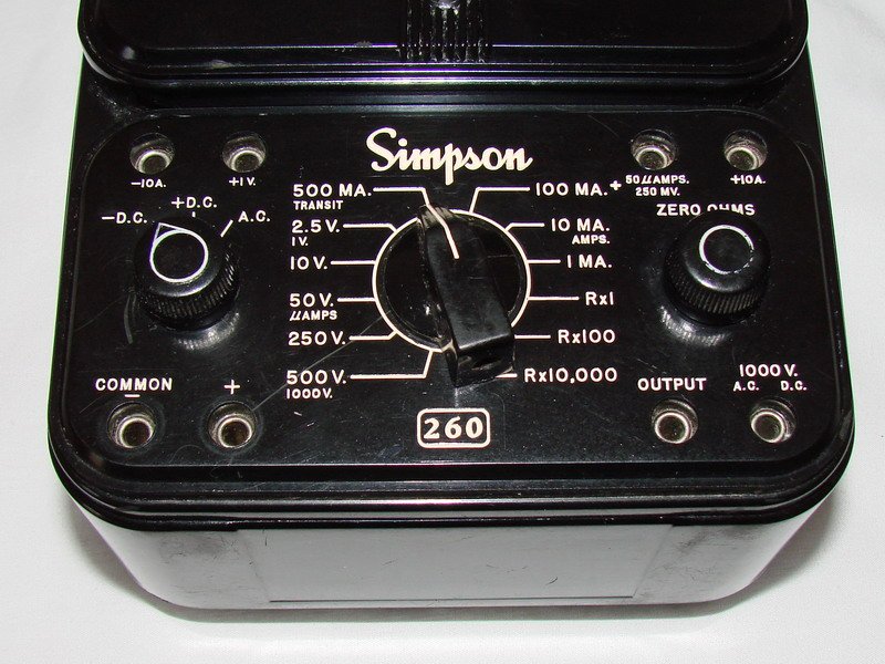
The 260’s front panel centers on a large rotary selector switch — not a lever, not a set of push-buttons — that carries the range legends silk-screened or engraved around its arc. Depending on series, function (DC/AC/Output/Ohms) and range (the specific full-scale value) may be combined on one switch or split across a main range switch plus a smaller AC-DC-Output/Ohms function switch; either way, every selection is made by rotating a knob to a printed legend, never by a slide, a toggle, or a push-button bank. Confusing this with a “lever-style” selector is the single most common misdescription of the 260’s front panel — it isn’t one.
4.3.2 The “start high, step down” rule
The 260 has no auto-range and — on the base (non-P) models — no electronic overload protection beyond fuses and the movement-protection diodes (Vol 2 §4, Vol 3). If you don’t already know roughly what you’re about to measure:
- Select the function first (DCV / ACV / DC mA / Ohms / Output).
- Select the highest range available for that function.
- Connect the leads and take a reading.
- Step the range down one position at a time until the pointer sits usefully far up-scale (roughly the upper two-thirds of the arc, where the % of full-scale accuracy spec translates into the best absolute accuracy).
Never do the reverse — guessing low and hoping — on an unknown circuit. A DC voltmeter range that’s too low for the actual voltage present, or a current range with the leads already in series in a live circuit, is exactly how you peg the needle against its stop or blow a fuse (§10 has the full DON’T list).
4.3.3 Jacks change with the range, not just the switch
Selecting a function on the rotary switch is only half the setup — on most ranges you also have to move the red lead to a specific jack (the black lead lives in −COMMON for essentially every measurement — see §8). Series 6 on, several ranges share a combined 1000 V AC/DC jack; the 5000 V range uses its own dedicated jack and an external accessory probe rather than the switch at all (§9). Check the jack legend next to wherever the red lead currently sits every time you change functions — it is easy to leave the red lead in, say, the 10 A jack from a prior current measurement and then rotate the switch to DC volts, which at minimum gives a meaningless reading and at worst subjects the shunt/jack wiring to a voltage it wasn’t expecting.
4.3.4 If you don’t know your unit’s exact jack layout
This volume assumes the Series 6-and-later jack arrangement Jeff’s own two units share, but the 260 lineage spans pin-type jacks (original/Series 2) through banana jacks (Series 3 on) to reverse-banana safety jacks (Series 7 on) — Vol 2 §6 has the full series-identification guide keyed off jack style, case, and dial markings. If you’ve picked up an earlier or unfamiliar 260 and aren’t certain which jack takes which lead for a given function, the safest habit is the same one that opens this section: select the function and range first, then look at the legend printed directly beside each jack rather than assuming a jack position carries over from a different series or a different instrument entirely. The function names (+DC, AC, OHMS, OUTPUT, ±10 A, 5000 V.) are consistent across the lineage even where the physical jack style underneath the label changed.
Table 1 — 3.4 If you don't know your unit's exact jack layout
| Jack style | Series | Lead type required |
|---|---|---|
| Recessed pin-type jacks | Original 260, Series 2/2A | Pin-type test leads (period part 0-008375) |
| Banana jacks | Series 3 on | Standard banana-plug test leads |
| Reverse-banana safety jacks | Series 7 on | Reverse-banana (shrouded) test leads |
| Combined 1000 V AC/DC jack | Series 6 on | Whatever lead type that series otherwise uses — this jack just consolidates what earlier series split across two positions |
4.4 DC Voltage
4.4.1 Range set
Table 2 — 4.1 Range set
| Range (V, full scale) | Accuracy | Sensitivity |
|---|---|---|
| 0–1 | 2% of FS | 20,000 Ω/V |
| 0–2.5 | 2% of FS | 20,000 Ω/V |
| 0–10 | 2% of FS | 20,000 Ω/V |
| 0–25 | 2% of FS | 20,000 Ω/V |
| 0–50 | 2% of FS | 20,000 Ω/V |
| 0–250 | 2% of FS | 20,000 Ω/V |
| 0–500 | 2% of FS | 20,000 Ω/V |
| 0–1000 | 2% of FS | 20,000 Ω/V |
| 0–250 mV (DC millivolts, separate position) | 2% of FS | 20,000 Ω/V |
(Series 8/8P Table 1-1; the 0–25 V step is itself a Series-8/8P addition — Vol 2 §“Series 8” — earlier series ran the classic 2.5-10-50-250-1000 ladder without the 25/500 intermediate steps.)
4.4.2 Procedure
- Rotate the selector to DC and the desired range (start high per §3.2 if unknown).
- Black lead into −COMMON. Red lead into the +DC jack (or the combined 1000 V AC/DC jack on the 500/1000 V ranges, Series 6 on).
- Touch the leads across the two points you want the potential difference between — red to the more positive point if you have a polarity guess, black to the reference/return. Getting it backward doesn’t damage anything on the DC volts function; the needle simply tries to swing left, off the mechanical stop, and you swap the leads (§8 covers this properly).
- Read the DC scale, using the mirror (§2.3) to kill parallax, at the range you’re on.
- Every 20,000 Ω/V figure means the meter itself is drawing current from the circuit under test — at the highest ranges this loading is negligible on stiff power-supply rails, but on a high-impedance node (a grid, a screen, a bias divider) it can pull the reading down measurably. That’s precisely the case where you reach for a VTVM instead — see the B&K 375 VTVM or Simpson 311-2 VTVM, both ~10–11 MΩ input, discussed at length in Vol 1.
Worked example — how much does 20,000 Ω/V actually load a circuit? On the 10 V range, the meter’s total input resistance is 10 V × 20,000 Ω/V = 200 kΩ. Bridging that 200 kΩ across a stiff, low-impedance node (say a filament winding or a regulated rail with a source impedance under a few hundred ohms) changes almost nothing — the voltage divider formed by the source impedance and the meter’s 200 kΩ barely moves. Bridge that same 200 kΩ across a 1 MΩ grid-bias divider, though, and the meter itself becomes a significant fraction of the divider — the reading sags well below the true open-circuit voltage. The rule of thumb: if the node’s own source impedance is within an order of magnitude of the meter’s range-dependent input resistance, expect meaningful loading error and reach for the higher-impedance VTVM alternative instead.
4.4.3 DC millivolts
The 0–250 mV position is a separate, dedicated low-range slot, not just “the bottom of the volts ladder” — useful for reading small shunt drops or low-level DC signals directly without an external divider. Same 20,000 Ω/V sensitivity applies; treat it with the same “start high, step down” discipline if the source is unknown, since 250 mV full scale pegs hard on anything even modestly above that.
4.5 AC Voltage
4.5.1 Range set and what “AC volts” actually measures
Table 3 — 5.1 Range set and what "AC volts" actually measures
| Range (V, full scale) | Accuracy | Sensitivity |
|---|---|---|
| 0–2.5 | 3% of FS | 5,000 Ω/V |
| 0–10 | 3% of FS | 5,000 Ω/V |
| 0–25 | 3% of FS | 5,000 Ω/V |
| 0–50 | 3% of FS | 5,000 Ω/V |
| 0–250 | 3% of FS | 5,000 Ω/V |
| 0–500 | 3% of FS | 5,000 Ω/V |
| 0–1000 | 3% of FS | 5,000 Ω/V |
The AC voltmeter function rectifies the input and feeds it to the same DC microammeter movement — Vol 3 covers the rectifier circuit (copper-oxide on the earliest series, germanium 1N87/1N270-class documented by Series 5) in full. The scale is calibrated to indicate the RMS value of a pure sine wave, but the movement actually responds to the average (rectified) value, referenced at 100 Hz.
Note — Because the calibration assumes a sine wave, a genuinely non-sinusoidal AC waveform (heavily clipped audio, an SCR-chopped light-dimmer output, a switching supply’s raw ripple) will read with extra error beyond the stated 3% — the meter has no way to know the waveform isn’t a sine. This is a characteristic of every average-responding meter, not a 260-specific flaw, but it’s worth knowing before you trust an AC reading on an obviously non-sinusoidal source.
For a pure sine wave, average (rectified) value and RMS value have a fixed, well-known ratio — RMS is 0.707 × peak, average of a full-wave-rectified sine is 0.637 × peak, so RMS ÷ average = 1.11. An average-responding meter’s scale is simply printed with that 1.11 “form factor” baked in, so it reads correctly for a sine without the movement itself ever computing anything resembling a true RMS value. Feed it a triangle wave, a square wave, or a heavily distorted signal and that fixed 1.11 factor no longer matches the real ratio between that waveform’s average and RMS — hence the caution above. A modern true-RMS DMM computes the actual RMS value regardless of waveform shape and won’t share this limitation, which is worth keeping in mind when a 260 AC reading and a true-RMS DMM reading on the same non-sinusoidal signal disagree — that disagreement is expected, not necessarily a fault in either instrument.
4.5.2 Procedure
- Rotate the selector to AC and the desired range.
- Black lead into −COMMON, red lead into the AC jack (combined with DC on the higher ranges, Series 6 on).
- AC has no “wrong way around” — the rectifier handles either lead orientation the same way, so polarity isn’t a concern here the way it is on DC (§8).
- Read the AC scale (a separate arc from the DC scale on most dial layouts — check you’re reading the scale labeled for AC, not the DC/current scale directly above or below it).
4.5.3 The aging tell
If AC readings drift low over years while DC volts and resistance on the same unit stay accurate, that’s the textbook symptom of an aging AC rectifier rising in forward resistance (Vol 3 §“AC rectifier”; Vol 5 §5 walks the replacement with a matched germanium diode). On the earliest series that means a copper-oxide rectifier; on Series 5-and-later — which covers every unit this volume is written against, Jeff’s Series 8 and 6P included — the AC circuit uses a germanium (1N87/1N270-class) diode instead, and it’s that diode’s forward resistance that drifts up with age. It’s mentioned here because it’s an operating observation, not just a repair fact — if two ranges on the same function disagree by more than the stated accuracy, or AC and DC readings on a known DC-only source disagree, that’s your first clue the rectifier (not the meter movement) is the suspect component.
4.6 DC Current — µA / mA / 10 A
4.6.1 Range set
Table 4 — 6.1 Range set
| Range | Accuracy | Voltage drop at full scale |
|---|---|---|
| DC Microamperes 0–50 µA | 1.5% of FS | 250 mV |
| DC Milliamperes 0–1 mA | 2% of FS | ≈250 mV |
| DC Milliamperes 0–10 mA | 2% of FS | ≈255 mV |
| DC Milliamperes 0–100 mA | 2% of FS | ≈300 mV |
| DC Milliamperes 0–500 mA | 2% of FS | ≈500 mV |
| DC Amperes 0–10 A | 2% of FS | ≈255 mV; not internally fused |
The current ranges are all built from an Ayrton/ring shunt across the 50 µA movement (Vol 3 §“DC current ranges”) — every range, including the 10 A range, is really the same movement with a different shunt in parallel, which is why the voltage drop (the “burden voltage”) stays in the 250–500 mV band across the entire span instead of ballooning at the high-current end the way a naive series-resistor approach would.
4.6.2 Procedure — this is the one function where you break the circuit
Unlike voltage (across two points) or resistance (across a de-energized component), a current measurement requires the meter to become part of the current path — you break the circuit open and insert the meter in series.
- De-energize the circuit before breaking it open. (§10 covers why this matters even more on the 10 A range specifically.)
- Rotate the selector to the current function and your best-guess range — start high per §3.2 if you don’t have a solid estimate of the current.
- Open the circuit at the point you want to measure (e.g., lift one leg of the load, or open the supply rail feeding it).
- Insert the meter leads into the break: red lead toward the more positive side (current conventionally flows red → black through the meter), black lead toward the return/ground side. Getting this backward drives the needle hard left against its stop — swap the leads rather than force it (§8).
- Re-energize, read the current scale (mirror technique, §2.3), then de-energize again before disconnecting.
- On the 0–10 A range specifically: never break the lead connection while the circuit is energized. That range is wired straight from the shunt to the ±10 A jacks with no fuse in the path — interrupting several amps at whatever voltage is present draws an arc across the opening contact, which is a burn/eye hazard and can weld or pit the jack/lead contacts. Power down, then disconnect. This is one of the hard DON’Ts in §10 — it’s repeated here because it’s the single most consequential procedural mistake available on this instrument.
4.6.3 µA and mA jacks vs. the 10 A jacks
The 0–50 µA through 0–500 mA ranges typically share the same set of jacks as the low-current DC function; the 10 A range uses its own dedicated ±10 A jacks, separate from the rest of the current ladder, precisely because that unfused path needs its own heavy-gauge internal wiring run straight to the shunt. Confirm you’re in the correct jack pair for the range you’ve selected before energizing anything — plugging into the 10 A jacks while the switch sits on a lower mA range (or vice versa) either reads nothing useful or, on the switch-still-on-10A/leads-in-low-range case, can dump far more current through a shunt sized for milliamps.
4.6.4 Burden voltage — why the meter isn’t “invisible” in a current measurement
Because every current range is really the same 50 µA movement behind a shunt, inserting the meter in series always inserts that range’s full-scale voltage drop (the “burden voltage,” 250–500 mV across the whole ladder, §6.1) into the circuit as well. On a supply rail running many volts, a few hundred millivolts of burden is noise. On a low-voltage circuit — say a 1.5 V battery-powered project, or a germanium-diode signal path where a couple hundred millivolts is a meaningful fraction of the whole swing — that burden voltage can measurably change the circuit’s own behavior while you’re trying to measure it, the current- measurement equivalent of the loading effect described for DC volts in §4.2. If a current reading seems to shift the circuit’s own operating point (a bias point moves, an oscillator’s frequency shifts, a regulator’s output sags) the moment you insert the meter, suspect burden voltage before suspecting the meter’s accuracy — it’s doing exactly what an ammeter with a nonzero internal resistance is supposed to do, just not always what the circuit under test can tolerate without complaint.
4.7 Resistance — and the Ohms-Zero Step That Doubles as a Battery Test
4.7.1 Range set
Table 5 — 7.1 Range set
| R × 1 | R × 100 | R × 10,000 | |
|---|---|---|---|
| Range | 0–2,000 Ω | 0–200,000 Ω | 0–20 MΩ |
| Center-scale reading | 12 Ω | 1,200 Ω | 120,000 Ω |
| Nominal open-circuit voltage | 1.5 V | 1.5 V | 9 V |
| Nominal short-circuit current | 125 mA | 1.25 mA | 75 µA |
| Arc accuracy | 2.5° | 2° | 2° |
Two internal batteries drive these three ranges (Series 6 on): a 1.5 V “D” cell (NEDA 13F) for R×1 and R×100, and a 9 V battery (NEDA 1604A) for R×10,000 — on P models the same 9 V also powers the electronic overload-protection relay (Vol 2 §4, Vol 3 §“Ohms circuit,” Vol 5 §2 for the battery-holder service itself).
4.7.2 The procedure — and why the zero step is not optional
Unlike volts and current, resistance is read on a reversed, non-linear scale: 0 Ω sits at the right-hand end of the arc (opposite the DC/AC zero at the left) and the scale compresses toward the left as resistance rises toward infinity. Zeroing this scale is a live electrical step, not a mechanical one, and it has to be repeated every time you change ohms range — the internal battery/shunt combination is different on each range, so a zero set on R×1 does not carry over to R×100 or R×10,000.
- Rotate the selector to the ohms function and the range you intend to use.
- Short the two leads together (touch the red and black tips to each other directly, or clip them together).
- Rotate the ZERO OHMS control until the pointer swings all the way to the right-hand zero mark of the ohms scale.
- If the pointer reaches zero cleanly, you’re calibrated for that range — separate the leads and measure your component (with the circuit de-energized — §7.4).
- Repeat steps 1–3 every time you switch between R×1, R×100, and R×10,000, and periodically during a session of ohms measurements as the battery sags.
⚠ Danger — Never attempt to zero, or measure, resistance on an energized circuit. The ohms function is applying its own internal battery voltage across whatever the leads touch; an external voltage already present on that node fights the internal battery, gives a meaningless reading, and can push current well outside what the ohms circuit and movement-protection diodes are sized for. Always de-energize and, on a circuit with capacitors, allow them to discharge before switching to ohms.
4.7.3 The battery-health test hiding inside the zero step
This is worth calling out on its own because it’s genuinely useful and easy to miss: the ohms-zero procedure IS the built-in battery test.
- If you cannot rotate ZERO OHMS far enough to reach the right-hand zero mark on R×1 or R×100, the 1.5 V D cell has sagged too far to drive the low-ohms ranges — replace the NEDA 13F D cell.
- If you cannot zero on R×10,000, the 9 V battery (NEDA 1604A) is the weak one — replace it. On a P model, a weak 9 V also degrades the overload-protection relay’s ability to trip and reset correctly, since that same battery powers the relay circuit (Vol 2 §4).
- If R×1/R×100 zero fine but R×10,000 won’t, you need only the 9 V, not the D cell, and vice versa — the two ranges are electrically independent, which is exactly why a failed zero on one range and not the other is diagnostic rather than ambiguous.
Vol 5 §2 covers the actual battery-holder service in depth — including the corroded-contact repair Jeff performed on his 6P, which is the other common reason a range won’t zero even with a fresh battery (a corroded spring clip is an open or high-resistance contact, indistinguishable from a dead cell until you’ve swapped the battery and it still won’t zero).
Note — Because zeroing is per-range and battery-dependent, get in the habit of zeroing immediately before each resistance measurement, not once at the start of a session. A battery that zeroed fine an hour ago can sag enough in the interim — especially a well-worn D cell — that the reading you’re about to trust is off. It costs two seconds.
4.7.4 What you’re actually measuring
Each range drives a known current through the unknown resistance (a fixed voltage source — the internal battery — through the range’s internal resistance) and reads the resulting deflection. That’s the whole reason the ohms function is also useful for basic component checks — a forward-biased diode, a good capacitor’s charge “kick,” or a transistor junction — beyond just measuring fixed resistors; Vol 1 covers the component-testing case for keeping an analog meter around, and Vol 3 has the ohms-circuit schematic detail. The operating discipline here is simply: zero every range, every time, and never do it live.
4.7.5 Reading the reversed, compressed scale
Unlike the DC/AC volts scale (linear, zero on the left, full-scale on the right), the ohms arc is non-linear and runs backward — zero sits at the right where you just zeroed it (§7.2), and resistance increases toward the left, compressing hard as it approaches infinity. Practically:
- The center-scale value differs by range — 12 Ω center on R×1, 1,200 Ω center on R×100, 120,000 Ω center on R×10,000 (§7.1 table) — because “center of the arc” is a fixed deflection, and each range’s internal current/voltage relationship maps that deflection to a different resistance value. Reading a component near the center of the arc, on whichever range puts it there, gives you the best accuracy (this is exactly the “start high, step down” logic from §3.2 applied to resistance — pick the ×1/×100/ ×10,000 multiplier that lands your unknown resistance near mid-scale, not jammed against either end).
- Near the right-hand (low-resistance) end, the scale is relatively open and easy to read precisely — good for spotting a near-dead-short or confirming continuity.
- Near the left-hand (high-resistance) end, the divisions compress dramatically — the difference between “very high” and “essentially open” becomes hard to resolve visually. If you need to distinguish, say, 15 MΩ from 18 MΩ, that reading is far more reliable on R×10,000 (where mid-scale is 120,000 Ω and 15–18 MΩ sits well up toward the compressed end but still on-scale) than trying to force it onto a range where it’s pinned hard left.
- No deflection at all, needle staying at the left-hand mechanical stop even after zeroing, reads as an open circuit (infinite resistance) on that range.
4.8 Polarity and COMMON−
4.8.1 The black lead’s job
For nearly every function on the 260, the black lead lives in the −COMMON jack and stays there; the red lead is the one that moves between jacks as you change function/range (+DC, the combined AC/DC jack, mA/µA, ±10 A, OUTPUT, or the 5000 V jack for the HV probe, §9). Get in the habit of setting the black lead once at the start of a session and leaving it, then only moving the red lead — it cuts the number of things that can be wrong in half.
4.8.2 What happens if you get DC polarity backward
On DC volts and DC current, the meter expects conventional current to flow red-lead-in, black-lead-out. Reverse it and the needle tries to deflect left, past the mechanical zero stop — it doesn’t read a negative number, it just jams against the stop (harmlessly at low currents/voltages, but not something to force or hold against repeatedly). If the needle slams hard left the instant you connect: stop, swap the leads, reconnect. This is normal and not a fault — it’s simply feedback that you guessed the polarity wrong.
On AC volts, AC current is not a function on this meter (there is no AC-current range on the base 260 — current measurement is DC-only), and on the ohms function, “polarity” in the DC-volts sense doesn’t apply the same way — the internal battery, not the external circuit, is the source, and the zero procedure in §7 is what matters, not lead orientation.
4.8.3 The meter floats
The 260 has no earth-ground reference of its own — −COMMON is simply the point you’ve chosen to call the return/reference for a given measurement, not a chassis or safety ground. This is what makes it usable for floating measurements (across a component that isn’t referenced to earth at all), and it’s also why the 1000 V circuit-to-ground rating (§10) is about the highest potential either lead can be at relative to true earth ground, not about some internal ground reference inside the meter.
4.9 Output Jack and Decibels
4.9.1 What OUTPUT is for
The Output function taps the AC voltmeter circuit through a series blocking capacitor, so it reads only the AC component of a signal that’s riding on a DC bias — the classic case being an audio output stage’s plate or collector, where you want the AC signal swing without the meter also trying to average in (or being damaged by) the DC operating point sitting underneath it.
Table 6 — 9.1 What OUTPUT is for
| Function | Ranges | Notes |
|---|---|---|
| Output Voltage (AC) | 0-2.5-10-25-50-250 | AC component only; DC blocking limited to 350 VDC |
⚠ Danger — The Output jack’s blocking capacitor is rated to block DC up to 350 VDC and no higher. Do not use the Output function on a node whose DC bias exceeds 350 V — that’s a job for the AC volts function on the combined high-voltage jack, or for the 5000 V HV probe (§9.3) if the AC signal you actually care about rides on a genuinely high DC rail. Exceeding the blocking cap’s rating risks breakdown of the capacitor and a DC path suddenly appearing where the meter isn’t expecting one.
4.9.2 Decibels
Table 7 — 9.2 Decibels
| dB range | 0 dB reference |
|---|---|
| −20 to +10 dB | |
| −8 to +22 dB | |
| 0 to +30 dB | |
| +6 to +36 dB | |
| +20 to +50 dB | 0 dB = 1 mW into 600 Ω |
The dB scale rides on the same AC/Output circuitry — it’s a logarithmic re-labeling of the AC voltage scale, referenced to 0 dB = 1 mW dissipated in a 600 Ω load, the classic telephone/audio-line reference impedance. Select the dB range the same way you’d select an AC volts range (start high, step down), and read the dB arc on the dial rather than the linear AC-volts arc. Because the reference assumes a 600 Ω load, a dB reading taken across an impedance that isn’t actually 600 Ω is still a valid voltage-ratio dB figure but isn’t a true power-level reading unless the load really is 600 Ω — worth remembering before quoting a dB number as an absolute power level on an arbitrary circuit.
The reference voltage behind “0 dB = 1 mW into 600 Ω” works out to √(0.001 W × 600 Ω) ≈ 0.775 V RMS — that’s the AC voltage which, dropped across an actual 600 Ω load, dissipates exactly 1 mW. Every other point on the dB scale is simply 20·log₁₀(V ⁄ 0.775 V) relative to that reference, which is why the scale is logarithmic rather than linear even though it’s derived from the same rectified-AC movement reading as every other AC measurement in this volume — the dial does the log conversion for you; you never compute it by hand on the bench, but it’s worth knowing where the 0 dB point actually comes from before trusting a dB figure on a load that isn’t 600 Ω.
4.9.3 Multiple dB ranges, one purpose
The five overlapping dB ranges (−20…+10, −8…+22, 0…+30, +6…+36, +20…+50) exist for the same reason the AC volts ladder has seven steps instead of one — each range corresponds to a different AC-volts full-scale position, so selecting a dB range is really selecting which AC volts range the dB scale is riding on top of for this particular signal level. A very low-level signal (a few mV) wants the lowest dB range for adequate resolution near mid-scale; a hot line-level signal wants a higher range so the needle doesn’t peg. The “start high, step down” habit from §3.2 applies here exactly as it does everywhere else on this instrument.
4.10 The 5000 V Range — External HV Probe
4.10.1 It is not a switch position
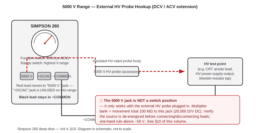
This is worth stating plainly because it’s the most commonly garbled fact about the 260’s range set: there is no 5000 V position on the rotary selector. The 5000 V capability is reached by plugging a dedicated external HV probe accessory into the “5000 V.” jack, which extends the existing DC (and AC) voltmeter multiplier chain out to that jack. The theory-of-operation math is the same 20,000 Ω/V relationship that defines the whole DC voltmeter: multiplier bank plus movement total 100 MΩ from the 5000 V jack to −COMMON, and 100,000,000 Ω ÷ 5000 V = 20,000 Ω/V — the same sensitivity figure that applies to every other DC range, just extended by an external multiplier stage living in the probe body itself rather than inside the meter case.
4.10.2 Procedure
- Confirm the high-voltage source is de-energized before connecting anything.
- Select DC (or AC, if the HV source is AC) on the rotary switch, at whatever range the probe’s markings call for — consult the probe’s own documentation for the exact multiplication factor and which range position to select, since this is an external accessory whose exact interaction with the switch position is specific to the probe model.
- Red lead into the 5000 V jack (not the ordinary +DC jack). Black lead stays in −COMMON as always.
- Connect the probe’s return/common lead to the circuit reference, then bring the probe tip to the HV test point — ideally with the probe body already connected and only the last hot connection made or broken with the source confirmed off, per one-hand-rule discipline (§11).
- Read the DC (or AC) scale, applying whatever multiplier the probe calls for on top of the switch range selected — refer to the probe’s markings rather than assuming a fixed ratio, since the exact accessory part number for this probe could not be confirmed against Simpson’s current catalog in this research (Vol 5 §8 flags this as an open item for parts sourcing).
- De-energize before disconnecting the probe.
4.10.3 Why this matters operationally
Because the 5000 V capability lives in an external accessory rather than the meter itself, the meter’s own 1000 V circuit-to-ground rating (§11) still applies to the meter case and the rest of its jacks even while the probe is extending the measurement range to 5000 V — the probe is specifically engineered (insulated body, internal multiplier) to keep the operator’s hand at a safe distance from the 5000 V potential while the meter itself never sees more than its ordinary internal voltages. Treat the probe, not the meter, as the high-voltage-rated component in this chain, and never substitute an ordinary test lead for the actual HV probe on a genuinely high-voltage source.
4.11 Safety — Ratings, Rules, and the DON’Ts
4.11.1 The headline rating
⚠ Danger — The 260 is rated 1000 V AC/DC, circuit-to-ground maximum (per ANSI C39.5, the standard cited in the Series 8/8P manual). That figure describes the highest potential difference the meter and its leads are built to withstand between either lead and true earth ground — it is not a statement about how much voltage the movement can read (the highest switch-selected range tops out well below that), and it is not raised by the 5000 V HV probe, which manages that higher potential through its own insulated body rather than by raising the base meter’s own rating.
4.11.2 One-hand rule
Above roughly 50 V, keep one hand in a pocket or behind your back while the other holds a probe — a shock
path across the chest (hand to hand) is far more dangerous than a path down one arm to the ground you’re
standing on. This is general bench-safety practice, not 260-specific, and it’s documented in the hub-wide
_shared/legal_ethics.md alongside the rest of the mains/HV/tube-era
discipline that applies across every instrument in this hub — read it once, apply it everywhere.
4.11.3 Treat everything as hot until proven otherwise
The 260 has no continuity light, no auto-range warning, and — on base (non-P) models — nothing electronic standing between you and an overload beyond the fuses and the movement-protection diodes. Assume any circuit you haven’t personally verified de-energized is live, and prove it’s dead with the meter itself (on an appropriate voltage range) before switching to ohms, before opening it for a current measurement, and before reaching in with your hands.
4.11.4 11.3a Inspect the meter itself, not just the circuit
The safety picture isn’t only about what’s on the other end of the leads. A 260 that’s decades old —
particularly an early series still wearing its original test leads — deserves a quick visual check before
each session: cracked or brittle lead insulation, a loose or wobbly banana/pin plug, a case with hairline
cracks near a jack, or corrosion visible through the battery/fuse door are all reasons to stop and repair
(Vol 5) before using the meter on anything above a few volts. Vintage test equipment in general can carry
hazardous legacy materials (old lead-tin solder, in some cases early phenolic/asbestos-filled moldings) —
the hub-wide _shared/legal_ethics.md document covers that material-
handling side of vintage-gear ownership; this volume’s concern is narrower and more immediate: don’t put a
compromised lead or a cracked case between yourself and a live circuit.
4.11.5 The DON’T table
Table 8 — 11.4 The DON'T table
| Don’t | Why | What actually happens |
|---|---|---|
| Measure resistance on an energized circuit | The ohms function applies its own internal battery voltage; an external voltage fights it | Meaningless/misleading reading; can force current beyond what the ohms circuit and protection diodes are sized for |
| Break the 10 A lead connection under load | The 0–10 A range is wired straight to the shunt with no internal fuse | Interrupting several amps under load draws an arc at the opening contact — burn/eye hazard, pitted/welded contacts |
| Use the Output jack above 350 VDC bias | The blocking capacitor is rated to block DC only to 350 VDC | Risk of capacitor breakdown, exposing the AC circuit to the full DC bias unexpectedly |
| Hold a probe in each hand above ~50 V | Creates a hand-to-hand (across-the-chest) shock path | The most dangerous current path through the body; use the one-hand rule (§11.2) |
| Assume a range is fused because another range is | The 10 A range is explicitly unfused even though F1/F2 protect most other ranges (Vol 2 §4, Vol 3) | False sense of security leads directly to the arc hazard above |
| Skip the ohms-zero step “because it zeroed last time” | Battery voltage sags during use, and zero is per-range | A stale zero silently biases every resistance reading taken after it |
| Force the needle against a stop (wrong polarity, over-range) | The movement and its stops aren’t meant to absorb sustained force | Bent pointer, jewel/pivot damage (pre-taut-band series especially), or a stressed taut-band suspension |
| Substitute an ordinary test lead for the 5000 V HV probe on a genuinely HV source | Ordinary leads have neither the insulation nor the internal multiplier of the actual probe | Direct exposure to the full HV potential at the operator’s hand |
| Use ohms to “check” a battery under its own power | The ohms function’s internal source fights the battery under test, and the reading doesn’t reflect the battery’s actual terminal voltage | Meaningless reading; possible current beyond the battery’s or the meter’s comfortable rating — use DC volts instead |
4.12 Measurement Selection at a Glance
A quick decision aid for “which function/range do I start on” — walk it top to bottom for an unfamiliar measurement:
                         ┌─────────────────────────────┐
                         │  What are you measuring?     │
                         └───────────────┬───────────────┘
                                         │
        ┌────────────────┬──────────────┼──────────────┬───────────────────┐
        ▼                ▼              ▼               ▼                   ▼
   Potential          Current         Resistance /     AC signal on a    Very high
   difference      (must break        component         DC bias           voltage
   across two        circuit open       check                             (>1000 V
   points, DC        & insert in                                          to ground)
        │            series, DC only)      │                 │                │
        ▼                ▼              ▼               ▼                   ▼
   Is source AC     Estimate current  De-energize     Select OUTPUT,     Use the 5000 V
   or DC?            first, start        circuit,       start high dB     HV probe in
        │            HIGH range         short leads,    range, DC bias    the 5000 V
   ┌────┴────┐        (§3.2, §6.2)     zero the ohms    must be ≤350 V    jack — this is
   ▼         ▼             │           range you'll        (§9)          an external
  DCV       ACV            ▼           use (§7.2)                        accessory, not
   │         │       10 A range?          │                                a switch
   ▼         ▼         │                  ▼                              position (§10)
 Start    Start        ▼             Reading won't
 HIGH     HIGH      NEVER break        zero on this
 range,   range,     this lead         range?
 red to   red to     under load           │
 +DC or   AC jack     (§6.2, §11)     ┌───┴───┐
 5000V    (§5.2)                      ▼       ▼
 jack                              R×1/R×100  R×10,000
 (§4.2,                            won't zero  won't zero
 §10)                                 │           │
                                      ▼           ▼
                                 Replace 1.5V   Replace 9 V
                                 D cell (13F)   battery (1604A)
                                 — Vol 5 §2     — Vol 5 §2
4.12.1 Measurement recipes
A few common bench tasks mapped straight to function/range/jacks, assuming a Series 6-or-later 260 (combined 1000 V AC/DC jack, TRANSIT position, D-cell + 9 V battery combo):
Table 9 — 1000 V AC/DC jack, TRANSIT position, D-cell + 9 V battery combo)
| Task | Function/range | Jacks | Notes |
|---|---|---|---|
| Check a wall outlet (~120 V AC) | AC V, 250 V range | Red: combined AC/DC jack · Black: −COMMON | Step down from a higher range only if the reading is comfortably low on the arc |
| Check a fuse or short length of wire for continuity | R×1, zeroed | Red/black leads | Circuit de-energized; reads ~0 Ω good, no deflection = open |
| Measure current draw of a small DC accessory | DC mA, start at 500 mA and step down | Red: mA jack · Black: −COMMON, in series with the supply lead | De-energize to break the circuit open first (§6.2) |
| Check a 9 V battery’s actual terminal voltage | DC V, 10 V range | Red: +DC · Black: −COMMON | Not the ohms function — see the DON’T table, §11.4 |
| Read an audio stage’s AC signal swing riding on a DC plate/collector voltage | OUTPUT, appropriate range | Red: OUTPUT jack · Black: −COMMON | Only if the DC bias is ≤350 VDC (§9.1) |
| Verify a battery is the reason an ohms range won’t zero | R×1/R×100 or R×10,000, attempt zero per §7.2 | Leads shorted together | Failure to zero on the low ranges = D cell; on R×10,000 = 9 V battery (§7.3, Vol 5 §2) |
| Measure a genuinely high-voltage node (>1000 V to ground) | DC or AC, per probe markings | Red: 5000 V jack, via HV probe · Black: −COMMON | External probe required — never bridge this with an ordinary lead (§10, §11) |
| Read the level of a line-level audio signal | dB, appropriate range | Red: OUTPUT/dB jack · Black: −COMMON | Only a true power-level reading if the load actually is 600 Ω (§9.2) |
| Confirm a capacitor isn’t shorted before powering up a restored circuit | R×10,000, zeroed | Red/black leads across the cap, circuit fully de-energized and cap discharged | Watch for the needle “kick” toward low resistance then relax back toward open as the cap charges from the internal battery — a healthy cap kicks and recovers; a shorted one stays low |
4.13 Care Between Sessions
The operating discipline in this volume doesn’t end when you set the leads down. A few habits from the manufacturer’s own maintenance guidance keep the meter ready for the next session instead of surprising you with a dead zero or a corroded battery compartment (Vol 5 covers the repair side of battery-holder corrosion in depth — this section is the preventive half):
- Set the switch to TRANSIT (Series 6 on) before storing or transporting the meter — §2.4.
- If the meter will sit unused for more than about 30 days, remove the batteries rather than leaving them installed. A cell that leaks while sitting idle in a drawer does its corrosion damage with nobody there to catch it early — this is exactly the failure mode behind the corroded battery holders Jeff repaired on his 6P (Vol 5 §2). If a unit has sat for a month or more with batteries still in, check the compartment for leakage signs (white/blue-green crust, a swollen cell) before assuming the batteries are still good.
- Replace batteries proactively rather than running them to failure. The manufacturer’s own guidance is blunt on this point: batteries should be replaced before their useful life has expired, because running them past that point is what invites leakage and corrosion, not just a weak reading. The ohms-zero test in §7.3 tells you a battery is already too weak to trust — treating that as your only battery-health signal means you’re finding out at the worst possible moment (mid-measurement) rather than proactively.
- Store the meter horizontal, matching its calibrated position, rather than propped on edge for extended periods — this is a minor point next to the battery guidance above, but it costs nothing and keeps the mechanical zero from Section 2.2 as stable as possible between sessions.
- Don’t leave leads plugged into a range’s jacks between sessions if the meter will be bumped, dropped in a bag, or otherwise handled roughly — an unattended lead is one more way to briefly short or load a circuit you didn’t mean to touch, and it’s an easy habit to build alongside setting TRANSIT.
4.14 Cross-References
- Vol 2 — the full series genealogy: which controls (TRANSIT, reset button, combined jacks) exist on which series, and why.
- Vol 3 — the schematic-level “why” behind everything operated in this volume: the multiplier ladder that makes 20,000 Ω/V work, the ohms circuit and its two batteries, the AC rectifier, and full detail on reading the mirrored/cascaded/reversed scales only briefly touched on here.
- Vol 5 — battery-holder service (including Jeff’s own 6P corrosion repair), range-switch contact cleaning, and the calibration/recalibration procedure that keeps the accuracy figures in this volume’s tables honest over decades of use.
- Vol 6 — the one-page cheatsheet distillation of the range set, the DON’Ts, and the battery-test logic from this volume, laminate-ready.
_shared/legal_ethics.md— the hub-wide bench-safety document (one-hand rule, mains/HV discipline, hazardous-materials notes on pre-1980s gear) referenced throughout §11.- B&K 375 VTVM and Simpson 311-2 VTVM — reach for either when the node under test is high-impedance enough that the 260’s 20,000 Ω/V loading would pull the reading down (§4.2).
Sources
- Simpson 260 Series 8 Instruction Manual (primary — Table 1-1 full range set, accuracy figures, voltage drops, 1000 V circuit-to-ground rating, Adjust-A-Vue handle, horizontal-calibration footnote): https://simpsonelectric.com/wp-content/uploads/File/260-8man.pdf
- Simpson 260 Series 8P Instruction Manual (primary — overload-protection self-test procedure, reset-button behavior, 9 V battery powering the relay circuit): https://simpsonelectric.com/wp-content/uploads/File/260-8Pman.pdf
- simpson260.com per-model pages (Series 6, 6P, 8, 8P) — panel photography confirming rotary-switch layout and range legends used in the verified images placed in this volume.
- Vol 2 (this dive) — The Series Genealogy, for full per-series control/feature changes.
- Vol 3 (this dive) — How It Works, for the circuit theory underlying every procedure in this volume.
- Vol 5 (this dive) — Refurbishing & Repair, for the battery-holder and range-switch service referenced from §7.3 and §12.1.