Simpson 260 Series 8 · Volume 5
Simpson 260 — Vol 5: Refurbishing & Repair
The battery compartment kills more 260s than sixty years of bench abuse ever did — here is how to bring one back.
5.1 Scope of this volume
This is the bench-repair companion to Vol 2 (genealogy), Vol 3 (circuit theory), and Vol 4 (operating procedure). Where Vol 4 tells you how to use the ohms-zero step as a battery check, this volume tells you what to do when that check fails, when the range switch goes intermittent, when the AC ranges quietly drift low, and — the single most common 260 repair — when the battery compartment has corroded shut.
Two units anchor the whole volume as running case studies: Jeff’s Series 8 (current diode-network movement protection, no relay) and his 260-6P (~1973, taut-band, fused and relay-protected). Where a procedure differs between them it is called out explicitly. Cross-references: battery chemistry and locations are per Vol 2 §“The ‘P’ suffix” and the technical facts battery table below; circuit context (where each battery feeds, why the movement needs protecting) is Vol 3 §“The ohms circuit” and Vol 3 §“Movement-protection diodes”; the ohms-zero-as-battery-test procedure is Vol 4 §“Resistance”.
Note — Every procedure below assumes the meter is unplugged from any circuit under test and the test leads are out of the jacks before you open the case. See the shared safety doc _shared/legal_ethics.md for general bench-discipline rules (mains isolation, one-hand rule, capacitor discharge) that apply to any vintage instrument on this bench, not just the 260.
5.2 Corroded battery holders — the #1 260 refurb
If there is one repair that defines “refurbishing a Simpson 260,” it is this one. Ask on any vintage-test- gear forum about a dead or erratic 260 and the first reply is almost always “check the battery compartment.” Jeff’s own 260-6P needed exactly this repair, and it is the case study that opens the volume.
5.2.1 Why the compartment corrodes
The 260’s ohms function runs on two batteries that live in a compartment accessible without a full teardown (Series 6 onward — see Vol 2 §6, the identification guide, where a separate battery/fuse door is itself a “Series 6 or later” tell). That accessibility is a double-edged sword: it makes battery swaps trivial, but it also means a leaking cell dumps its electrolyte directly onto exposed spring-steel contacts instead of being buried in a sealed compartment.
The failure chain is mechanical, not electrical:
- A cell — usually the 1.5 V D cell, sometimes the 9 V — is left in the meter past its useful life or during long storage. The instruction manual actually calls this out directly (§1.6 below quotes it verbatim): batteries left in too long, or a meter stored more than 30 days without checking, are the textbook precondition for leakage.
- Alkaline electrolyte (potassium hydroxide, a caustic salt once it dries) seeps out of the cell’s seam and wicks across whatever metal it touches.
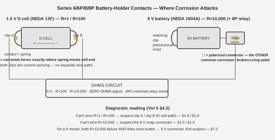
- Because the D-cell holder’s spring clips are the electrical contacts — not a separate holder with wires running to remote contacts — the leakage attacks the exact metal that has to carry current cleanly to the ohms circuit. Corrosion products are non-conductive or poorly conductive, so the fault presents as “ohms won’t zero” or “ohms function dead” long before it presents as anything visibly dramatic.
- The 9 V’s polarized snap connector is smaller and often closer to the cell body, so it can also corrode, or the leak can migrate to it across the compartment floor.
Note — This is not a Series-8-only or Series-6-only problem. It is a design characteristic of the whole spring-clip-as-contact approach used from Series 6 through Series 8/8P and beyond (see §1.2). The earlier soldered-in-battery series avoided this exact failure by avoiding user-serviceable batteries altogether, at the cost of needing a full teardown for any battery service at all — see Vol 2 §1 and §“Case/body variants.”
Why it’s specifically the spring clips that die, not the PCB traces nearby: an alkaline cell’s electrolyte is potassium hydroxide (KOH) solution. While liquid, it’s mainly a housekeeping nuisance — wipe it up and move on. The damage accumulates once it’s had time to dry and react. KOH reacts with atmospheric CO₂ to form potassium carbonate, and it reacts directly with the zinc alloy and steel it contacts to form a crust of metal oxides/hydroxides — the white-to-gray, sometimes greenish, crystalline growth every 260 owner eventually recognizes on sight. That crust is mechanically fragile and electrically resistive. On a spring-steel contact whose entire job is to press two clean metal surfaces together with tens of milliohms of contact resistance, even a thin film of that crust is enough to turn a solid electrical connection into an intermittent one — long before the spring itself has lost any measurable amount of base metal. This is why a compartment can look only lightly corroded and still produce a completely dead ohms function: the fault is a surface-contact problem, not a bulk-metal-loss problem, at least in the early stages. Left long enough, the crust and the acidic-to-basic corrosion cycle will eat through thin spring steel, which is when clean-in-place (§1.4) stops being sufficient and holder replacement (§1.5) becomes the only real fix.
5.2.2 The original holder design (Series 6 / 6P / 8 / 8P)
The Series 8 and 8P instruction manuals describe the holder in identical language (§1.3 of each), and it matches what Jeff found inside his 6P:
“There are two batteries in the ohmmeter circuits. One is a NEDA 13F size D cell that furnishes 1.5-volts for the R×1 and R×100 ranges. A NEDA 1604 battery furnishes 9-volts for the R×10,000 range. The 1.5-volt D cell is held in place with two spring clips which also serve as battery contacts … The 9-volt battery is held in place with a spring clip, but contact is made with a separate connector that is polarized.”
Unpacked:
- 1.5 V D cell (NEDA 13F): retained end-to-end by two spring-steel clips — one at each end of the cell. Both clips are current-carrying. There is no separate “holder” plastic part doing the mechanical job while wires do the electrical job; the springs do both.
- 9 V battery (NEDA 1604 / 1604A): held down by a single spring clip for mechanical retention, but the actual electrical connection is the familiar polarized snap connector (the same style found on every 9 V-battery-powered consumer device) wired into the ohms/protection circuit.
- On the 260-8P, the 9 V battery does double duty — it also powers the electronic overload-protection relay (Vol 2 §“The ‘P’ suffix”; Vol 3 §“Movement-protection diodes”). A corroded 9 V connector on a P model can therefore take out both the R×10,000 range and the reset-button protection circuit at once, which is a useful diagnostic tell: if the reset button won’t reliably latch/reset and R×10,000 won’t zero, look at the 9 V connector first.
5.2.3 Case study — Jeff’s 260-6P
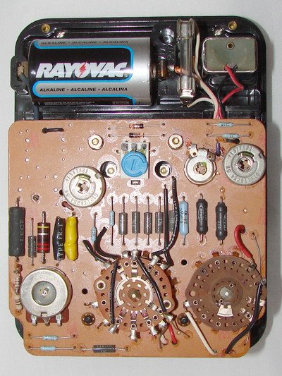
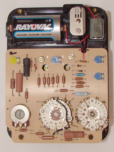
Case study — Jeff’s 260-6P. The 6P’s battery holders had corroded to the point of unreliable contact — the exact failure mode described in §1.1, on the exact holder geometry described in §1.2. Jeff replaced the corroded holders rather than attempt an in-place clean-and-hope; see §1.5 for the replacement approach used. The before/after photos of this specific repair are the single most valuable image this volume is missing — see the figure slot immediately below.
5.2.4 Cleaning corrosion in place
Not every corroded compartment needs full holder replacement. If the spring steel itself is still sound — pitted but not perforated or snapped — an in-place clean can restore reliable contact:
- Remove both batteries and photograph the compartment before touching anything (useful for a before/after record and for re-checking polarity later).
- Neutralize the alkaline residue. Alkaline-cell leakage is a caustic (basic) salt, so it responds to
a mild acid or a chemical neutralizer, not to solvent alone:
- White vinegar on a cotton swab, worked into the visible corrosion, or
- Baking-soda paste — this is the more common recommendation specifically because baking soda is itself mildly basic and some collectors prefer it paired with a vinegar rinse step, but plain vinegar alone is the more direct neutralizer for alkaline (not acid) leakage. Either is reported as effective in the collector literature; the point is to stop reacting with fresh electrolyte before you start scrubbing.
- Rinse. Water rinse to carry away the neutralized salts and any loosened crust.
- Flush and dry with isopropyl or denatured alcohol. This displaces the water (which you do not want sitting on bare steel or PCB traces) and evaporates cleanly, leaving no residue.
- Burnish the spring contacts. A fiberglass scratch brush, a pencil eraser, or fine (400–600 grit) wet-or-dry paper worked gently on the contact faces removes the thin oxide/corrosion film and restores bright metal. Don’t remove more material than necessary — these are thin spring-steel clips, not sacrificial contacts.
- Finish with DeoxIT. A drop of DeoxIT D-series (or equivalent contact-protectant) on the burnished contact leaves a thin conductive film that resists re-oxidation. This is the same product and the same logic used on the range-switch wafer in §2 — DeoxIT is the one consumable that shows up in essentially every 260 service write-up.
- If a clip was physically removed for cleaning, it can be soaked in vinegar, rinsed, and alcohol-dried the same way before reinstalling.
Note — Preventive maintenance from the manual itself (§5.6, quoted below in §1.6) is the cheapest fix of all: this whole failure mode is avoidable by not leaving batteries in a meter that’s going into storage.
5.2.5 Holder replacement / modern equivalents
When the spring steel itself is corroded through, has lost its temper (won’t hold tension against the cell anymore), or the polarized 9 V snap connector’s crimped-on wire has broken, cleaning in place isn’t enough. Simpson’s original clip part numbers were not found in any source consulted for this dive — Simpson never published a discrete parts list for the holder hardware itself, only the battery types that go in it (§1.2). Collectors have converged on two practical approaches instead:
- Fabricate or source generic springy-steel battery clips sized to the D-cell and 9 V footprints and solder/rivet them onto the original contact points, matching the original geometry.
- Wire in a small commodity battery holder (a standard AA/D holder shell, or a 9 V clip-lead pigtail) to the original PCB/contact points, effectively replacing the compartment hardware with an off-the-shelf part while keeping the original battery type and location the manual specifies.
Either approach is documented in the collector repair literature — the element14 “Simpson Model 260 Series 5 Repair” write-up walks a full contact rebuild, and antiqueradios.com threads titled “Simpson 260 Battery Connector Clips” and “series 6 battery clips” cover sourcing discussions for exactly this part. The common thread across all of them: nobody sources an exact Simpson replacement clip, because Simpson never sold one as a spare part — everyone either rebuilds the spring steel or substitutes a generic holder.
5.2.6 Preventive maintenance (from the manual)
Simpson’s own instruction manual addresses this directly, in language that reads like it was written for this exact failure (§5.6):
“Remove batteries if storing more than 30 days; check for leakage if the instrument has not been used for 30 days … batteries should be replaced before their useful life has expired — failure to do so may result in corrosion and battery leakage.”
Translated to a bench habit: pull the D cell and 9 V any time the 260 is going into a drawer for more than a month, and when you do leave batteries in, don’t run them to exhaustion — a battery near end-of-life is disproportionately more likely to leak than a fresh one under light intermittent load.
5.2.7 Compartment service, step by step
A consolidated walkthrough tying §1.4 (clean) and §1.5 (replace) into one bench procedure — this is the sequence Jeff followed on the 6P, adapted to whichever outcome the inspection in step 3 points toward.
- Isolate the meter. Test leads out of every jack, meter not connected to any circuit under test.
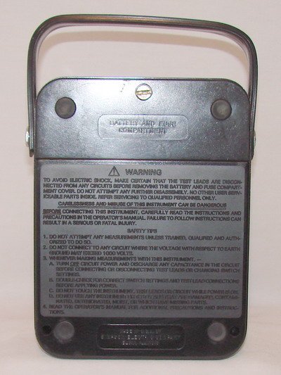
- Open the battery/fuse compartment. On Series 6-and-later this is the single captivated screw behind the small door (§6.2 covers the fuse side of the same compartment) — you do not need to remove the full back cover to reach the batteries on these series, which is one of the Series-6 improvements flagged in Vol 2.
- Remove both batteries and inspect before touching anything else. Look specifically at:
- the two D-cell spring clips (§1.2) for white/gray crust, pitting, or a clip that’s visibly lost its spring tension (sits loose against the cell rather than pressing firmly),
- the 9 V’s polarized snap connector for the same crust, or for a crimp that’s come loose from its lead,
- the compartment floor and any nearby PCB trace for migrated residue. A phone photo here is worth taking even if you’re confident — it’s the only record you’ll have of “as found” condition, and it’s the photo this volume’s figure slot (§1.3) is asking for.
- Decide clean-in-place vs. replace, per the criteria in §1.4/§1.5: sound spring steel with surface crust → clean in place; steel that’s lost temper, corroded through, or a connector with a broken/ corroded crimp → replace.
- Execute §1.4 or §1.5 as decided.
- Before reinstalling batteries, verify contact geometry by eye — clips should grip a test cell (or the old cell, if it wasn’t the leaker) with visible spring tension, not just touch it.
- Install fresh batteries, correct polarity (the 9 V connector is keyed and should only mate one way — if it seats with noticeable resistance or an odd angle, stop and recheck the connector rather than forcing it).
- Close the compartment and run the ohms-zero check on all three ranges (§4.2) before considering the job done. A compartment that looks perfectly clean can still have a bad contact — the zero check is the actual proof, not the visual inspection.
- Log it. Per the project’s engineer’s-logbook convention (see the hub
CLAUDE.md), record what was found, what was done, and the before/after ohms-zero result — not just “cleaned battery contacts.”
5.2.8 Tools and consumables for this section
Table 1 — 1.8 Tools and consumables for this section
| Item | Purpose |
|---|---|
| Small Phillips/flat driver matching the compartment’s captivated screw | Opens the battery/fuse door |
| Cotton swabs | Applying vinegar / baking-soda paste precisely |
| White vinegar or baking-soda paste | Neutralizing alkaline residue (§1.4) |
| Isopropyl or denatured alcohol | Rinse-and-dry flush after neutralizing |
| Fiberglass scratch brush, pencil eraser, or 400–600 grit wet-or-dry paper | Burnishing spring contacts back to bright metal |
| DeoxIT (D-series or equivalent) | Protective film on cleaned contacts — also used in §2 on the range switch |
| Fresh NEDA 13F (D) and NEDA 1604A (9 V, alkaline) batteries | For the post-service functional check (§1.7 step 7–8) — don’t test with the old, possibly-marginal cells |
| Phone/camera | Before/after documentation |
5.3 Range-switch wafer / contact oxidation
5.3.1 Symptom
Intermittent readings on some ranges but not others, a reading that jumps or drops out when you nudge the selector knob, or a noisy/unstable ohms-zero that won’t settle — these all point at the rotary range-selector switch (Vol 3 covers its role in the circuit; Vol 4 covers normal operation). The switch is a mechanical wafer with multiple contact rings; every position change wipes a spring contact across a fixed pad, and over years those pads pick up a thin oxide film exactly like any other unused or lightly used contact.
5.3.2 Construction, by era
- Later series (Series 3 onward, once the PCB was introduced): plastic wafer switches mounted on or near the printed circuit board — visible in both internals photos above (§1.2). This is the construction in both of Jeff’s units.
- Earliest series (pre-PCB, the original 260): extensive hand-wiring, no PCB, and correspondingly no wafer-on-PCB switch of this style — see Vol 2 §1. A pre-Series-3 meter’s switch service looks different and is out of scope for the wafer-specific procedure below.
The switch does two jobs at once on the 260, and it’s worth keeping both in mind when you’re chasing an intermittent range: it’s both the function selector (DC/AC/output/ohms) and the range multiplier selector within a function. A contact that’s marginal on, say, the 250 V DC position but fine everywhere else is telling you the fault is localized to one ring/position, not the whole switch assembly — useful information before you start spraying cleaner at the whole thing.
Table 2 — 2.2 Construction, by era
| Era | Switch construction | Practical implication for service |
|---|---|---|
| Original 260 (Series 1) | Hand-wired, no PCB, no wafer-style switch as described here | Different service approach entirely — inspect individual soldered contacts, not a wafer |
| Series 2/2A | Molded case, engraved lettering — switch construction detail not separately documented in the sources behind this dive | Treat cautiously as pre-PCB-era construction until inspected |
| Series 3 onward | PCB introduced; wafer-style rotary switch mounted on/near the board | §2.3 procedure applies directly |
| Series 6/6P/8/8P (Jeff’s units) | Plastic wafer switch on PCB, visible in the internals photos (§1.2); “transit” position (Series 6-on) and “OFF/transit” (Series 7-on) add extra switch positions to cycle through | §2.3 procedure applies directly; more positions to cycle in step 3 below |
5.3.3 Fix and discipline
- Use a contact cleaner meant for electronics — DeoxIT D5 (the same family used on the battery clips in §1.4) or an equivalent TV-tuner/contact cleaner. Do not substitute a general-purpose degreaser or solvent not rated for electronic contacts; some attack the plastic wafer material itself.
- Apply sparingly. A light spray or a wetted swab directly on the contact ring — flooding the switch lets cleaner run into the phenolic/PCB and adjacent components, which you don’t want.
- Cycle the switch through every position, repeatedly. This is the step that actually does the work — the wiping action of the contact against the pad, lubricated by the cleaner, is what removes the oxide film. A single spray with no cycling does very little.
- Wipe excess after cycling so no cleaner is left pooling.
- Finish with DeoxIT as a protective film, same rationale as the battery contacts.
⚠ Danger — Don’t over-lubricate a switch that also carries the higher-voltage AC/DC ranges (up to 1000 V circuit-to-ground on Series 8 — Vol 4 §“Safety”). Excess liquid contact cleaner bridging adjacent wafer positions is a leakage path you don’t want on a switch carrying line-connected voltages.
5.4 Meter-movement issues
5.4.1 Pivot-and-jewel wear (pre-taut-band units)
Every series through Series 5’s base models rides on pivot-and-jewel D’Arsonval bearings (Vol 2 §3); these are mechanically delicate compared to what came after. A meter that’s been dropped, shipped carelessly, or simply lived a long working life on a pivot-and-jewel movement can develop:
- A sticky or dragging pointer — the jeweled bearing surface is worn or chipped, adding friction that a taut-band suspension simply doesn’t have.
- A bent pointer from physical shock — visually obvious, and the manual is explicit that you should not run the meter with broken meter glass (§5.2), since a cracked or missing glass leaves the pointer and movement exposed to further damage and contamination.
5.4.2 Taut-band units (Series 6 onward)
Series 6 and later — including both of Jeff’s units — use taut-band suspension instead of jeweled pivots (Vol 2 §3; the “taut-band trap” callout there explains why this did not start on Series 8). A taut-band movement suspends the moving coil on a stretched metal ribbon rather than a pivot riding in a jewel cup, and it is substantially more shock-resistant and self-shielding. This is a meaningful practical advantage for a field instrument that gets carried, dropped, and knocked around a bench — it’s a large part of why a Series 6-or-later 260 is the more forgiving instrument to own and use hard.
The mechanical difference explains why it’s more robust, not just that it is: a pivot-and-jewel movement has a hard, small-radius bearing surface (the pivot tip) riding inside an even harder, small jewel cup — a classic point-contact bearing, which is precise but concentrates any shock load onto a tiny contact area capable of chipping the jewel or blunting the pivot. A taut-band suspension instead supports the coil on a thin, pre-tensioned metal ribbon (or pair of ribbons) under mild torsional spring load — there’s no point-contact bearing to shock-load at all, and the ribbon itself provides the restoring torque that used to come from a separate hairspring. Two direct service consequences follow: a taut-band movement doesn’t develop the friction/stiction failure mode described in §3.1 (there’s no jeweled bearing to wear), but a taut-band ribbon can fail differently — an overstressed or fatigued ribbon can go slack or snap, which shows up as a pointer that swings freely with no restoring force, or one that’s stuck against a stop. That failure mode is a movement-replacement job, not a field adjustment, on either of Jeff’s units.
5.4.3 Magnet aging
The permanent (Alnico) magnet in any D’Arsonval movement weakens very slightly over decades of storage and use, which shows up as a small systematic drift in the movement’s sensitivity — typically read as slightly-high indications relative to a fresh reference. This is not 260-specific; it is general D’Arsonval-movement behavior. It is not something to chase with a screwdriver — it’s corrected the way any gain drift is corrected, through the calibration procedure in §4, not by trying to re-energize or replace the magnet.
5.5 Zeroing & calibration
5.5.1 Mechanical zero
Before any measurement, with no leads connected, the pointer should rest exactly on the left-hand zero mark. If it doesn’t, the small screw-slot adjuster below the meter face (standard practice on essentially every panel-meter movement, and present on the 260’s face) turns the pointer to true zero. This is a five-second check worth doing at the start of every session, not just after a repair.
5.5.2 Ohms zero — the built-in battery test
Vol 4 covers this as a normal operating step; it belongs here too because it is simultaneously the fastest battery-health diagnostic the meter has. For each ohms range: short the leads together and rotate ZERO OHMS until the pointer reads 0 Ω (the right-hand end of the ohms scale).
- If you cannot zero R×1 or R×100 → the 1.5 V D cell is exhausted or its contact is bad. Given §1, “bad contact” is at least as likely a culprit as “dead cell” on an older meter — check the battery under load with an independent meter before assuming the cell itself is the problem.
- If you cannot zero R×10,000 → the 9 V battery is exhausted or its polarized connector is bad. On a P model, remember the 9 V also feeds the overload-protection relay (§1.2) — if the reset button is also misbehaving, that’s corroborating evidence pointing at the 9 V connector rather than the cell itself.
5.5.3 Recalibration against a reference
For a full recalibration (not just the zero check), the practical bench approach:
- Reference equipment: a trusted digital multimeter and a set of precision resistors (or a stable, known voltage source for the voltmeter ranges).
- Orientation matters. The 260 is specified and calibrated with the instrument horizontal — Vol 3 notes this as a stated accuracy condition, not a suggestion. Recalibrating (or even just spot-checking) with the meter propped at an angle introduces error the procedure isn’t accounting for.
- Check near full scale. Because 260 accuracy specs are stated as a percentage of full scale (Vol 3’s range table — 2% DCV, 3% ACV, etc.), a spot check near the low end of a range tells you very little; the absolute error budget is the same in µA/mV terms across the whole range, so it’s a much larger percentage error near the bottom of the scale. Compare against the reference near the top of each range.
Worked example — spot-checking a Series-8 DC volts range against a reference DMM:
Table 3 — Worked example — spot-checking a Series-8 DC volts range against a reference DMM:
| Step | Action | Example numbers |
|---|---|---|
| 1 | Set the 260 to a DC volts range, meter horizontal | 250 V range selected |
| 2 | Apply a known, stable DC source near the top of that range through both the 260 and the reference DMM in parallel | Bench supply set to ≈240 V |
| 3 | Read the reference DMM | 240.3 V (assume DMM accuracy is well inside the 260’s 2% budget) |
| 4 | Read the 260’s needle against its scale | 238 V |
| 5 | Compute the error against full scale, not against the reading | (240.3 − 238) / 250 = 0.92% of FS |
| 6 | Compare against the spec | 0.92% is inside the 2%-of-FS spec for DC volts (Vol 3’s range table) — no adjustment needed |
The reason step 5 divides by full scale (250 V) rather than by the reading (240.3 V) is the same percentage-of-full-scale point made above — a 2.3 V discrepancy would look like nearly 1% error if you (incorrectly) divided by the reading on a low-range check, but the meter’s spec is against full scale, so that’s the denominator that actually tells you whether the unit is in tolerance. If the computed error exceeds the specified percentage, that range (and ideally the adjacent ranges sharing the same multiplier stage — see Vol 3’s voltmeter-ladder diagram) needs the corresponding trimmer adjusted per §4.4, or — if no trimmer exists for that series — component-level attention.
5.5.4 Trimpots by series
- Series 1 has no calibration trimpots at all — Vol 2 confirms the original 260’s construction is extensive hand-wiring with no PCB and no trimpots. There is nothing to trim; any recalibration on an original 260 is a component-level exercise (replacing precision multiplier/shunt resistors), not a screwdriver adjustment.
- Later series (from the PCB-equipped Series 4 onward, per the calibration-circuit PCB introduced there — Vol 2 §2) carry internal trimmers or factory-selected resistors intended for periodic adjustment. Simpson’s own guidance is to return the meter annually to an authorized service center or the factory for check/adjust/calibrate — the exact published cal test-point values live in Simpson’s service/repair manual (not the operator’s manual), and were not machine-readable in the research pass behind this dive; treat published cal-point numbers as something to pull from that document directly rather than from this volume.
5.5.5 Post-repair verification checklist
A short, repeatable sequence to run after any service work in this volume — battery holders, switch cleaning, rectifier swap, fuse replacement — before calling the meter back in service:
- Mechanical zero with no leads connected (§4.1).
- Ohms zero on all three ranges — R×1, R×100, R×10,000 (§4.2). This alone catches most battery/ holder/connector faults.
- On a P model, run the overload self-test (§7.2) — confirms the reset button and relay path are healthy, and indirectly confirms the 9 V connector if the ohms-zero on R×10,000 already passed.
- Spot-check one DC volts range and one AC volts range near full scale against a reference (§4.3’s worked example) — catches a rectifier or multiplier-resistor problem that a simple zero check won’t reveal.
- Cycle the range switch through every position once, listening/feeling for a clean detent at each stop — catches a switch problem introduced or missed during the work.
- Close up, and log the before/after state per the hub’s engineer’s-logbook convention.
5.6 AC rectifier replacement
5.6.1 The aging story
Vol 3 covers the AC signal path in detail: AC is rectified to feed the same 50 µA DC microammeter that does everything else, and the meter responds to the average of the rectified waveform, calibrated to read the RMS value of a pure sine at a 100 Hz reference frequency. The rectifying element itself changed over the model’s life (Vol 2’s series-change summary table):
- Early series used a copper-oxide (metal-oxide) rectifier — confirmed directly from an early 260 operator’s manual: “A.C. is rectified by a copper oxide rectifier in order to supply the microammeter with direct current.”
- By Series 5, the manual specifies a 1N87 germanium diode. Germanium’s low forward drop (roughly 0.2–0.3 V, versus a silicon diode’s ~0.6 V) keeps the low AC ranges linear at small signal levels — a genuine electrical reason for the choice, not just parts availability.
- The exact copper-oxide-to-germanium cutover series is not confirmed in the sources behind this dive — don’t assert a specific series as “the” transition point beyond “copper-oxide on the earliest units, germanium documented by Series 5.”
5.6.2 The failure mode and the diagnostic
Copper-oxide rectifiers age: their forward resistance rises over decades of shelf and service life, which is a slow, silent failure. Because it degrades rectifier efficiency rather than open-circuiting outright, the symptom is specific and diagnostic:
The “AC-reads-low” diagnostic: if a 260’s DC voltage ranges and ohms ranges check out accurately against a reference, but the AC voltage ranges read progressively low (and non-linearly, worse toward the low end of a range) — suspect an aged copper-oxide rectifier before suspecting anything else in the circuit. DC and ohms don’t touch the rectifier at all, so a fault isolated to AC-only, with DC/ohms clean, points straight at that one component.
5.6.3 The fix
Replace the aged rectifier with a matched germanium diode in the 1N87/1N270 class (1N270, 1N100, 1N276, 1N34A are the commonly cited germanium substitutes in the collector literature). Two things matter more than the exact part number:
- Watch polarity. Getting the rectifier backward doesn’t just fail to fix the AC-reads-low symptom, it can send the AC path’s rectified current the wrong way through the microammeter.
- Match the forward-drop characteristics reasonably well — the reason germanium was chosen originally (§5.1) is the reason a silicon substitute is a poor choice here; a silicon diode’s higher forward drop will reintroduce nonlinearity at the low end of the AC ranges even with a perfectly healthy part.
Why forward drop matters so much on a 260 specifically: the AC voltmeter path shares the same 250 mV full-scale movement drop used everywhere else on the meter (Vol 3). On the lowest AC volts range, the rectified signal at the movement can be comparable in magnitude to the diode’s own forward drop — so the diode isn’t a small correction sitting in an otherwise-linear signal chain, it’s a meaningful fraction of the whole reading budget on that range. A qualitative comparison of the two families:
Table 4 — the whole reading budget on that range. A qualitative comparison of the two families
| Rectifier type | Typical forward drop | Effect on low-end AC accuracy | Aging behavior |
|---|---|---|---|
| Copper-oxide (earliest series) | Low when new, but rises with age | Good when new; degrades over decades | The classic slow failure — this is what §5.2 diagnoses |
| Germanium (1N87/1N270-class, by Series 5) | ~0.2–0.3 V | Stays linear at low signal levels | Comparatively stable; the modern-collector default replacement |
| Silicon (general-purpose 1N400x-class, etc.) | ~0.6 V | Poor — reintroduces nonlinearity/low-reading error at the low end of AC ranges | Stable, but the wrong electrical characteristic for this specific job |
The takeaway for a repair bench: don’t reach for “whatever diode is in the parts drawer” here. A 1N4148 or 1N400x will pass current in the right direction and look like a fix on a quick smoke-test, but it will leave the low AC ranges reading measurably wrong in a way that’s easy to miss unless you specifically spot-check the low end of an AC range against a reference (§4.5’s checklist step 4 exists partly for this reason).
5.7 Fuse replacement
Fuses are Vol 3 circuit-theory content and Vol 4 operating-procedure content as well; this section is the service-and-sourcing view.
5.7.1 Part numbers (Series 8 / 8P, and by extension 6/6P/7/7P which carry the same two-fuse scheme)
Table 5 — 6.1 Part numbers (Series 8 / 8P, and by extension 6/6P/7/7P which carry the same two-fuse scheme)
| Fuse | Rating | Type | Exact replacement | Interrupting capacity |
|---|---|---|---|---|
| F1 | 1 A, 250 V | 3AG, quick-blow | Littelfuse 312001 only — Simpson specifies this part by name | up to 250 V |
| F2 | 2 A, 600 V | high-energy | Littelfuse Type BLS or Bussmann Type BBS | 10,000 A up to 600 V |
⚠ Danger — F1’s replacement is not “any 1 A 3AG fuse” — Simpson’s manual names the Littelfuse 312001 specifically. F2’s interrupting-capacity rating (10,000 A up to 600 V) is doing real work protecting against a high-energy fault; a generic fast-blow fuse with the right current rating but a much lower interrupting capacity is not an equivalent substitute on that position.
5.7.2 What’s fused and what isn’t
- The 0–10 A current range is NOT internally fused. The 10 A shunt is wired directly to the ±10 A jacks. This is a deliberate design choice (a fuse in that path would itself be a failure point at 10 A), but it means the operator is the fuse — see Vol 4’s DON’T table for the corollary: never break a 10 A lead connection while the circuit is energized, because there’s no fuse to interrupt an arc.
- Where the fuses live: the battery/fuse compartment (the same door shown in §1.2’s third photo), behind a single captivated screw. The 1 A fuse (F1) sits in a small rotating cup — press then rotate to access it, rather than a simple pull.
- A spare 1 A fuse ships in the compartment from the factory. If a meter arrives with no spare in the slot, that’s a sign a prior owner already used it — worth checking F1 itself while you’re in there.
- Diagnostic: if the meter won’t read at all on ranges that should be fuse-protected, check F1 or F2 before assuming a deeper fault — a blown fuse is a much more common cause of “totally dead” than a failed movement or a cracked PCB trace.
5.8 Overload-protection service on P models
5.8.1 What’s actually being serviced
Vol 2 §“The ‘P’ suffix” lays out that protection is layered, not a single gadget: fuses (crude, Series 6-on), a diode/clamp network protecting the movement directly (Series 8-on), and — the actual “P” feature — a resettable relay/transistor cutout with a front reset button (first on the 5P, 1968). On the 260-8P specifically:
- A transistor circuit senses the voltage drop across the movement through a bridge network, so the protection works regardless of which polarity the overload arrives on.
- It trips the relay at approximately 3× the range’s rated full scale.
- Relay contacts sit in the −COMMON circuit and latch open on a trip — they stay open, not just momentarily interrupted, until the operator intervenes.
- The front-panel reset button pops up roughly 3⁄16 inch above the panel on a trip — a visible, physical tell that the meter got hit hard enough to need it, not just an internal relay click.
- Not every range is covered. The electronic protection explicitly excludes the 1 V, 10 A, 50 µA, 250 mV, and the 500 V/1000 V AC and DC ranges — those rely on the fuses and diodes alone (§6, and Vol 3). Don’t assume “it’s a P model” means every range is relay-protected; it doesn’t.
5.8.2 Servicing implications
- The 9 V battery powers the relay circuit (§1.2 again — this is why a corroded 9 V connector on a P model is a double failure). A latch-out switch is designed to stop battery drain once the relay has tripped, so a tripped-and-unreset meter shouldn’t itself be the reason the 9 V goes flat, but a marginal/corroded 9 V connection can still cause erratic relay behavior independent of the battery’s actual charge state.
- The audio continuity alarm on the 8P is not protected by the electronic overload system — it’s a separate circuit and doesn’t get the benefit of the relay cutout.
- Self-test procedure (from the 260-8P manual, §1.4): set the function to R×10,000 and −DC, then touch the black lead (plugged into COMMON) to the +1 V input jack. The reset button should visibly rise, proving the protection circuit is functional — and Simpson states explicitly that no damage results from this test, making it a safe, repeatable functional check after any service work on a P model.
- On the 6P specifically: the reset button sits just left of the Simpson logo — the same physical location described for the current 8P and consistent across the P-model line. If Jeff’s 6P repair (§1.3) involved the 9 V connector at all, the self-test above is the right verification step once the new holder is in and a fresh 9 V is installed.
5.8.3 How the protection mechanism itself differs, 5P → 6P → 8P
Because Jeff owns a 6P and this volume treats it as a running case study, it’s worth being precise about which protection generation his unit actually has versus what the current 8P manual describes — the two are related but not identical, and a repair note that quotes 8P-manual specifics on a 6P risks overstating what’s confirmed for that specific series (Vol 2’s genealogy notes flag this explicitly).
Table 6 — 7.3 How the protection mechanism itself differs, 5P → 6P → 8P
| Series | Protection mechanism | Component-level detail | Confidence |
|---|---|---|---|
| 5P (1968, first “P”) | Transistorized relay circuit, reset button on the left side | Simpson never published this board’s parts list; collector-documented production-run variation (some boards one transistor, some two) | Mechanism confirmed; components uncertain |
| 6P (Jeff’s unit, ~1973) | Base 260-6 already carries fuses (1 A behind the battery/fuse door, 2 A behind the back cover); 6P adds the resettable overload circuit on top, reset button just left of the Simpson logo | Circuit-level detail beyond “resettable relay + reset button” not separately documented from the 8P in the sources behind this dive | Mechanism confirmed; exact component values not separately confirmed for the 6P vs. 8P |
| 8P (current production) | Diode network (movement protection) + resettable relay via bridge-sensing transistor circuit + two fuses + reset button + audible continuity buzzer | Full mechanism and exclusion list (§7.1) is primary-sourced from the 260-8P manual | Fully confirmed, primary source |
The practical service takeaway: the self-test procedure in §7.2 is documented for the 8P specifically (from the 8P manual’s own §1.4). It is reasonable to try the same test sequence on the 6P by analogy — set R×10,000, touch the black lead to +1 V, watch for the reset button to rise — since the underlying mechanism (transistor-sensed overload tripping a relay in the −COMMON path) is the same concept across the P-model line. But treat that as an analogous procedure on the 6P, not a manual-quoted one; if the 6P’s button doesn’t respond to the exact 8P self-test conditions, that alone shouldn’t be read as a confirmed fault without corroborating evidence (fuse check, 9 V check, physical relay click if audible).
5.9 Parts sourcing today
The good news for anyone servicing a 260 in 2026: Simpson Electric is still in business and the 260-8 line is current production (Vol 2 §7).
Table 7 — 8. Parts sourcing today
| Part | Source / spec | Notes |
|---|---|---|
| Test leads | Simpson Catalog No. 00043 — one red + one black, 48″, combination probe-tip + removable rubber-sleeved screw-on alligator clips; rated 1000 V AC/DC, 10 A | Fits 260-7/8/9 and many 270/360/460-family models; widely restocked (Newark, Mitchell Instrument, Techni-Tool) |
| Older-series leads | Cat. No. 00125 (48″, Series 3–6) · Cat. No. 02055 (36″, early 260) with clip set 01927 | Per simpson260.com’s accessories page |
| Low-ohms battery (R×1/R×100) | NEDA 13F, 1.5 V D cell | Ordinary retail item — Simpson’s own manual states batteries are “standard items replaceable from local retail stores” |
| High-ohms battery (R×10,000) | NEDA 1604A, 9 V, alkaline specified | On P models this also feeds the overload relay — use alkaline as specified, not zinc-carbon |
| F1 fuse | Littelfuse 312001, 1 A/250 V, 3AG | §6.1 |
| F2 fuse | Littelfuse BLS or Bussmann BBS, 2 A/600 V | §6.1 |
| AC rectifier (repair) | Germanium diode, 1N87/1N270-class (1N270, 1N100, 1N276, 1N34A all cited as substitutes) | §5.3 |
| 5000 V HV probe | Extends DC/AC voltage measurement via the “5000 V” jack | Exact current Simpson catalog/part number is unconfirmed — a commonly repeated “00033” figure could not be verified against Simpson’s current accessory list; do not treat that number as confirmed |
| Manufacturer contact | Simpson Electric Company, Lac du Flambeau, WI; (715) 588-3311; simpsonelectric.com | Current 260-8/8P manual footer; also sells a Renew Kit for the 260-8 series |
Note — The manual’s own operator part number for the 8P is 6-114339, in case you need to reference the exact document Simpson ships with a current unit when ordering parts or asking their service line a question.
5.9.1 Parts NOT confirmed sourceable
Being straightforward about the gaps matters as much as listing what’s available:
- Original spring-clip battery-holder hardware (§1.5) — no Simpson part number was found in any source consulted for this dive. Every documented repair uses either a rebuilt/fabricated clip or a substituted commodity holder, never a Simpson-sourced replacement clip.
- Replacement movements / NOS parts — available informally through Simpson service and the used/collector market, but no public part numbers were captured in the research behind this volume. If a movement itself needs replacing (bent taut-band ribbon per §3.2, or a badly worn pivot-jewel per §3.1), expect to go through Simpson’s own service department rather than a generic parts catalog.
- Detailed calibration test-point values — as noted in §4.4, these live in Simpson’s service/repair manual, not the operator’s manual this volume draws most of its primary detail from.
5.9.2 When to send it out rather than DIY
Every procedure in this volume assumes a competent bench technician working carefully with common hand tools and contact-cleaner-grade chemicals. Two situations are worth calling out as reasonable points to stop and send the unit to Simpson’s service department (or a specialist vintage-test-equipment repair shop) instead of pushing further on the bench:
- A taut-band ribbon has failed (§3.2) — this is a precision mechanical part with no published Simpson spare-part number, and a botched field replacement risks turning a repairable meter into an unrepairable one.
- A calibration is out of spec on a series without accessible trimpots, or the drift is large enough that it looks like a precision multiplier/shunt-resistor problem rather than a simple trim (§4.4) — this is component-level work against values that aren’t published in the operator’s manual, and Simpson’s own guidance is annual factory/service-center check-and-adjust for exactly this reason.
Everything else in this volume — battery holders, switch contacts, fuses, the rectifier, and routine zero/calibration checks — is squarely within reach of a home bench, and is exactly the kind of work that keeps a 260 that’s been in service since the 1970s (like Jeff’s 6P) still earning its place on the bench today.
5.10 Failure-mode reference table
A single lookup table synthesizing every section above — the table to reach for mid-repair.
Table 8 — 9. Failure-mode reference table
| Symptom | Likely cause | Section | Fix |
|---|---|---|---|
| Ohms won’t zero on R×1/R×100 | 1.5 V D cell exhausted or its spring-clip contact corroded | §1, §4.2 | Replace D cell; if contact is suspect, clean (§1.4) or replace holder (§1.5) |
| Ohms won’t zero on R×10,000 | 9 V battery exhausted or polarized connector corroded | §1, §4.2 | Replace 9 V (alkaline); clean/replace connector |
| Ohms won’t zero on R×10,000 and reset button misbehaves (P models) | 9 V connector fault — shared supply for ohms and relay | §1.2, §4.2, §7.2 | Service the 9 V connector; re-run the self-test in §7.2 |
| Visible white/crusty residue in battery compartment | Leaked cell — alkaline electrolyte | §1.1 | Neutralize + clean (§1.4) or replace holder (§1.5) |
| Reading jumps, drops out, or is noisy on some range positions when the selector is nudged | Range-switch wafer contact oxidation | §2 | DeoxIT + cycle the switch (§2.3) |
| Pointer sticky, drags, or won’t settle (pre-taut-band unit) | Worn/chipped pivot-and-jewel bearing | §3.1 | Service is a movement-level repair; not a field fix — compare against a taut-band unit’s robustness (§3.2) |
| Pointer bent | Physical shock; possibly cracked meter glass | §3.1 | Do not operate with broken glass; repair/replace movement |
| Reads slightly high across ranges vs. a reference, broadly consistent | Alnico magnet aging | §3.3 | Correct via recalibration (§4.3), not by chasing the magnet |
| DC and ohms accurate, AC volts reads progressively low, worse at low end of range | Aged copper-oxide rectifier | §5 | Replace with matched germanium diode, 1N87/1N270-class, correct polarity |
| Meter totally dead on fused ranges | Blown F1 or F2 | §6 | Check/replace F1 (Littelfuse 312001) or F2 (BLS/BBS) before suspecting the movement |
| 10 A range lead arced/damaged when disconnected under load | 10 A range is not fused — operator is the fuse | §6.2 | No fix but caution: never break a 10 A connection while energized |
| Relay trips repeatedly / reset pops on moderate signals | Overload circuit doing its job (~3× FS trip point) or a marginal component in the sense bridge | §7.1 | Confirm the actual signal level first; if trips are unexplained, verify 9 V health (§1.2) and run the self-test (§7.2) |
| Won’t recalibrate — no trimpots found | Series 1 unit — no trimpots exist by design | §4.4 | Any adjustment on a Series 1 is component-level (multiplier/shunt resistors), not a screwdriver trim |
5.11 Battery complement by series — quick refurb reference
Reproduced from the technical facts battery table (Vol 2 covers the same ground genealogically; this is the refurb-oriented version — what to actually buy).
Table 9 — 10. Battery complement by series — quick refurb reference
| Series | Low-ohms battery (R×1 / R×100) | High-ohms battery (R×10,000) | Holder style |
|---|---|---|---|
| Original 260 (Series 1) | one 1.5 V “C” cell | two 3 V cells (Eveready 905 / 750-class, ≈6 V total) | Soldered in — no user-serviceable holder; battery replacement is a teardown job |
| Series 5 | one 1.5 V “D” cell | ~6 V pack (four AA cells or equivalent) | [UNCERTAIN whether 4×AA is the original factory holder or a common collector workaround] |
| Series 6 / 6P / 7 / 8 / 8P (Jeff’s units) | 1.5 V “D” cell, NEDA 13F | 9 V battery, NEDA 1604 / 1604A (alkaline) | Spring-clip D-cell contacts + polarized 9 V snap connector — the compartment this whole volume is about |
⚠ Danger — Do not substitute a “15 V” or “30 V” battery on any 260 R×10,000 circuit on the strength of a forum comment. Neither figure is confirmed for the 260 in any source behind this dive — the modern high-ohms battery is 9 V, full stop, on Series 6 and later. A 15 V figure occasionally seen online most likely refers to a different Simpson (or other manufacturer’s) meter with a different ohms range, not the 260.
5.12 Where this leaves Jeff’s two units
- The 260-6P: battery-holder corrosion repaired (§1.3) — this volume’s headline case study. Worth a follow-up pass through §2 (range switch) and §4 (zero/calibration check with the new holder installed) now that the compartment has fresh contacts, since a full ohms-zero check across all three ranges is the cheapest way to confirm the repair actually restored clean electrical contact and not just a visually-clean compartment.
- The 260-8: no corrosion history reported, but the same holder geometry (§1.2) means the same preventive-maintenance habit (§1.6) applies — pull the batteries for any extended storage. As the currently-produced design lineage (Vol 2 §7), it’s also the unit for which spares (§8) are least in doubt.
For high-impedance nodes where the 260’s 20,000 Ω/V loading is the wrong tool regardless of how well it’s been refurbished, reach for the B&K 375 VTVM or the Simpson 311-2 VTVM instead — see Vol 1’s when-to-use discussion for the full reasoning.
5.13 Tools, consumables & shop discipline — the whole-volume checklist
A single shopping list and discipline summary spanning every section above, useful to print or keep next to the bench before starting any 260 service session.
5.13.1 Consumables
Table 10 — 12.1 Consumables
| Consumable | Used in | Notes |
|---|---|---|
| White vinegar or baking-soda paste | §1.4 | Neutralizes alkaline (KOH) corrosion — don’t substitute an unrelated household cleaner |
| Isopropyl or denatured alcohol | §1.4, general contact drying | Displaces water, evaporates clean |
| DeoxIT (D-series contact cleaner/protectant) | §1.4 (battery clips), §2.3 (range switch) | The one consumable common to nearly every 260 service write-up consulted |
| Fine wet-or-dry paper (400–600 grit) or fiberglass scratch brush | §1.4 | Burnishing spring contacts — go easy, these are thin springs, not sacrificial pads |
| Fresh NEDA 13F (D) + NEDA 1604A (9 V, alkaline) | §1.7, §4.5 | Always verify a repair with fresh batteries, never the batteries that may have caused the fault |
| Littelfuse 312001 (F1), Littelfuse BLS / Bussmann BBS (F2) | §6.1 | Keep spares on hand — a spare F1 originally ships in the compartment |
| Germanium diode, 1N87/1N270-class | §5.3 | Do not substitute silicon — see §5.3’s forward-drop table |
5.13.2 Tools
Table 11 — 12.2 Tools
| Tool | Used in |
|---|---|
| Small driver matching the battery/fuse compartment’s captivated screw | §1.7 |
| Cotton swabs | §1.4 |
| Reference DMM + precision resistors / stable voltage source | §4.3, §4.5 |
| Phone/camera for documentation | §1.3, §1.7 |
| Soldering iron (holder replacement / rectifier swap only) | §1.5, §5.3 |
5.13.3 Shop discipline, restated
- Isolate before opening — leads out, meter disconnected, every time (Scope note at the top of this volume).
- Photograph before you clean, replace, or desolder anything. The single best insurance against a reassembly mistake, and it’s the same habit that produces the before/after record the Vol 5 figure slot (§1.3) is built around.
- Verify with the ohms-zero check, not by eye. A visually clean compartment or a freshly-cycled switch is not proof of a fix — §4.2 and §4.5 exist because the electrical proof and the visual impression can disagree.
- Match original part characteristics, don’t just match ratings. The rectifier forward-drop discussion (§5.3) and the fuse-type discussion (§6.1) both make the same point from different angles: “close enough on paper” parts can leave a working-but-subtly-wrong instrument, which is worse than an obviously-dead one because it’s more likely to go unnoticed on the next measurement.
- Log everything, per the hub convention — before/after values, not just “fixed the battery contacts.”
Sources
- Simpson 260 Series 8 Instruction Manual (primary — battery/holder description §1.3, fuse part numbers §1.2, preventive-maintenance §5.6, “do not run with broken glass” §5.2): https://simpsonelectric.com/wp-content/uploads/File/260-8man.pdf
- Simpson 260 Series 8P Instruction Manual (primary — overload-protection mechanism §1.2, self-test procedure §1.4, 9 V/relay relationship §1.3): https://simpsonelectric.com/wp-content/uploads/File/260-8Pman.pdf
- Early 260 operator’s manual excerpt — copper-oxide rectifier description (ManualsLib): https://www.manualslib.com/manual/1385338/Simpson-260.html?page=11
- simpson260.com — Series 1, 5, 6, 8 model pages and internal/battery-compartment photos: https://www.simpson260.com/260-1/simpson_260-1a.htm , https://www.simpson260.com/260-5/simpson_260-5.htm , https://www.simpson260.com/260-6/simpson_260-6.htm , https://www.simpson260.com/260-8/simpson_260-8.htm
- element14 — “Simpson Model 260 Series 5 Repair” (contact-rebuild write-up, battery clips, switch): https://community.element14.com/technologies/test-and-measurement/b/blog/posts/simpson-model-260-series-5-repair
- eevblog forum — “Simpson 260-3” repair thread (internals, corrosion, switch service): https://www.eevblog.com/forum/repair/simpson-260-3/
- Smokstak forum — “Simpson 260 volt Ohm meter corrosion” (member photos of corroded compartment): https://www.smokstak.com/forum/threads/simpson-260-volt-ohm-meter-corrosion.217837/
- antiqueradios.com — “Simpson 260 Battery Connector Clips” and “series 6 battery clips” (sourcing discussion): https://antiqueradios.com/forums/viewtopic.php?t=259945 , https://antiqueradios.com/forums/viewtopic.php?f=8&t=344316
- antiqueradios.com — germanium-diode rectifier substitutes discussion: https://antiqueradios.com/forums/viewtopic.php?t=183560
- Simpson Electric — current 260-8/260-8P product page and Renew Kit (manufacturer, primary): https://simpsonelectric.com/products/test-equipment/vom-multimeters/260-8-260-8p/
- Simpson Electric — accessories/test-lead datasheet: https://simpsonelectric.com/wp-content/uploads/File/datasheets/testleads.pdf
- Newark / Mitchell Instrument — Simpson 00043 test-lead kit listings: https://www.newark.com/simpson/00043/test-lead-kit/dp/62F3012 , https://www.mitchellinstrument.com/replacement-simpson-test-lead-set-reverse-insulated-00043.html
- Internal cross-references: this dive’s Vol 2 (Series Genealogy — §“The ‘P’ suffix”, §“Movement evolution”, §“Case/body variants”, §“Series-identification guide”), Vol 3 (How It Works — ohms circuit, AC rectifier path, movement-protection diodes), Vol 4 (Using the 260 — resistance/ohms-zero procedure, safety DON’Ts on the 10 A range).