Simpson 260 Series 8 · Volume 6
Simpson 260 — Vol 6: Cheatsheet (laminate)
Every spec, battery, fuse, series tell, and DON'T on one bench sheet — no photos, all tables.
6.1 Purpose & How to Use This Sheet
This volume is a synthesis, not a source — it distills Vols 2–5 into lookup tables for the bench. Every row that states a fact carries a “detail:” pointer back to the volume and section where the full explanation, the caveats, and the confidence-tagged sourcing live. If a number here disagrees with your memory of Vol 2–5, the earlier volume wins — this sheet is compressed for speed, not for nuance.
Laminate rule of thumb: if you only keep one section taped inside the lid, make it §14 (Safety DON’Ts) and §5 (Series-ID Quick Key) — those are the two most likely to prevent damage to the meter or to you.
Note — Zero photos in this volume by design. It’s meant to survive a laser printer and a lamination pouch; halftones don’t. For visual ID references (dial photos, panel photos, case photos) see Vol 2.
6.2 Why Reach for This Meter (30-second version)
Table 1 — 1. Why Reach for This Meter (30-second version)
| Analog trait | Why it matters on the bench | Detail |
|---|---|---|
| Needle shows rate + direction of change | Peaking, nulling, dip-finding (alignment, bridge nulls, tuning) — trivial on a swinging needle, painful watching jumping DMM digits | Vol 1 |
| Mechanical inertia smooths a noisy signal | A flickering/fluctuating reading settles to a mean instead of strobing through random digits | Vol 1 |
| Ohms ranges drive a known current | Test diodes both directions, transistor B-E/B-C junctions, watch a cap “kick” and discharge — real hands-on component testing a DMM’s near-zero-drive ohms function can’t do the same way | Vol 1, Vol 3 §6 |
| No warm-up, no battery for V/I ranges | Works instantly, works when a DMM’s battery is dead | Vol 1 |
| Lower input impedance (20 kΩ/V) | Actually rejects ghost/phantom voltages that fool a 10 MΩ DMM — loads out induced/leakage voltage so a real source shows real current draw | Vol 1 |
| Rugged, RFI-tolerant, sunlight-readable | Field-serviceable characteristics a digital display doesn’t share | Vol 1 |
Note — This is not “vs DMM, which wins” — it’s “which tool for which node.” For high-impedance nodes (grids, screens, AVC lines) the 260’s 20 kΩ/V loading is a liability, not an asset — reach for the B&K 375 VTVM or Simpson 311-2 VTVM instead. Detail: Vol 1.
6.3 Headline Specs
Table 2 — 2. Headline Specs
| Parameter | Value | Detail |
|---|---|---|
| Movement | D’Arsonval moving-coil, 50 µA full scale, 250 mV drop at FS | Vol 3 §1 |
| DC sensitivity | 20,000 Ω/V | Vol 3 §3 |
| AC sensitivity | 5,000 Ω/V (average-responding, sine-RMS calibrated, 100 Hz reference) | Vol 3 §5 |
| DC volts accuracy | 2% of full scale | Vol 3 §3 |
| AC volts accuracy | 3% of full scale | Vol 3 §5 |
| DC current accuracy | 2% of full scale (1.5% on the 50 µA range) | Vol 3 §4 |
| Ohms center-scale (R×1 / R×100 / R×10,000) | 12 Ω / 1,200 Ω / 120,000 Ω | Vol 3 §6 |
| Rated circuit-to-ground voltage | 1000 V AC/DC max (per ANSI C39.5) | Vol 4 §9 |
| Case (Series 8/8P) | 5½″ × 7″ × 3″, 3 lb, heavy-wall phenolic | Vol 2 §5 |
| Calibrated position | Horizontal — accuracy is specified with the meter lying flat | Vol 3 §1 |
| Movement suspension (Series 8) | Taut band, standard | Vol 2 §3 |
| Dial (Series 8) | Mirror-backed, tri-colored, standard (why “8” has no “M”) | Vol 2 §3 |
| Movement protection (base 8 / 8P) | Diode network (both) + resettable relay, ~3× FS trip (8P only) | Vol 2 §4 |
| Current status | Still in production — 260-8 / 260-8P / 260-8MCS / 260-9S / 260-9SP | Vol 2 §7 |
Note — “20,000 Ω/V” is a derived number, not a knob setting: the multiplier bank plus the movement total 100 MΩ from the “5000 V.” jack to COMMON−, and 100,000,000 Ω ÷ 5000 V = 20,000 Ω/V. Detail: Vol 3 §3.
6.4 Full Range Set — Series 8 / 8P
Table 3 — 3. Full Range Set — Series 8 / 8P
| Function | Ranges | Accuracy | Notes | Detail |
|---|---|---|---|---|
| DC Volts | 0-1-2.5-10-25-50-250-500-1000 V | 2% FS | 20,000 Ω/V; 5000 V via external HV probe only — not a switch position | Vol 3 §3, Vol 4 §8 |
| DC Millivolts | 0-250 mV | 2% FS | shares the 20,000 Ω/V ladder | Vol 3 §3 |
| AC Volts | 0-2.5-10-25-50-250-500-1000 V | 3% FS | 5,000 Ω/V; average-responding, sine-RMS calibrated | Vol 3 §5 |
| Output (AC) | 0-2.5-10-25-50-250 | — | AC component only; blocks up to 350 VDC | Vol 3 §7 |
| DC Microamperes | 0–50 µA | 1.5% FS | the base movement current; 250 mV drop | Vol 3 §4 |
| DC Milliamperes | 0-1-10-100-500 mA | 2% FS | drop ≈250/255/300/500 mV across the ranges | Vol 3 §4 |
| DC Amperes | 0–10 A | 2% FS | ≈255 mV drop; shunt wired straight to the ±10 A jacks — NOT fused | Vol 3 §4, §12 below |
| Decibels | −20…+50 dB across 5 ranges | — | 0 dB = 1 mW into 600 Ω | Vol 3 §7 |
| Resistance R×1 | 0–2,000 Ω | 2.5° arc | 1.5 V open-circuit, 125 mA short-circuit | Vol 3 §6 |
| Resistance R×100 | 0–200,000 Ω | 2° arc | 1.5 V open-circuit, 1.25 mA short-circuit | Vol 3 §6 |
| Resistance R×10,000 | 0–20 MΩ | 2° arc | 9 V open-circuit, 75 µA short-circuit | Vol 3 §6 |
Note — The 0–25 V AC/DC range and the mirrored dial are the two features that specifically mark a Series 8 (new vs. Series 7). Detail: Vol 2 §2, §4.
6.5 Battery Complement by Series
Table 4 — 4. Battery Complement by Series
| Series | Low-ohms battery (R×1 / R×100) | High-ohms battery (R×10,000) | Notes | Detail |
|---|---|---|---|---|
| Original 260 (Series 1) | one 1.5 V “C” cell, soldered in | two 3 V cells (Burgess 422 / Eveready 750 or 905), ≈6 V total, soldered in | no back-cover access — full teardown to service | Vol 2 §1, §2 |
| Series 2–5 | one 1.5 V “D” cell | ~6 V pack (commonly 4× AA in series) | Series-5 wording is ambiguous on whether 4×AA is original or a common workaround — [UNCERTAIN] | Vol 2 §2 |
| Series 6 / 6P / 7 / 7P / 8 / 8P | one 1.5 V “D” cell, NEDA 13F | one 9 V battery, NEDA 1604 / 1604A (use alkaline) | Series 6 is the first to standardize the D + 9 V combo; on P models the 9 V also powers the overload relay | Vol 2 §2, Vol 5 §1 |
⚠ Danger — Do not use “15 V” or “30 V” for any 260 high-ohms battery — those figures are unverified for this instrument and likely a mix-up with a different Simpson/other-brand meter. The Series 6-and-later high-ohms cell is 9 V, full stop. Detail: Vol 2 §2.
Battery-holder mechanics (Series 6/8, the ones you’ll actually service):
Table 5 — Battery-holder mechanics (Series 6/8, the ones you'll actually service):
| Cell | Holder | Failure mode |
|---|---|---|
| 1.5 V D cell | Retained by two spring-steel clips that are themselves the contacts | Leaked electrolyte corrodes the clips → intermittent or dead R×1/R×100 |
| 9 V | Spring clip plus a separate polarized snap connector | Corroded snap → dead R×10,000 and, on P models, a relay that won’t hold reset |
Detail: Vol 5 §1 (this is Jeff’s actual 6P repair — full before/after case study there).
Coarse era tell: soldered 3 V + C-cell → original; D + 4×AA → Series 2–5; D cell + 9 V → Series 6-on. Detail: Vol 2 §6.
6.6 Series-ID Quick Key
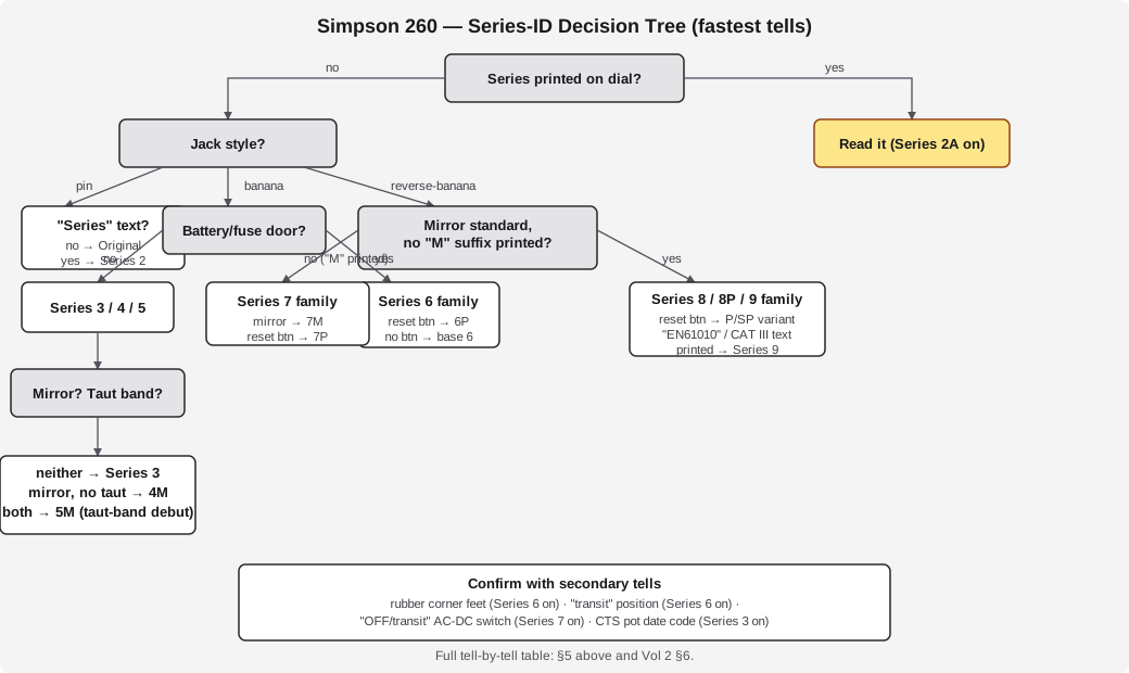
Ordered fastest-tell to finest. Work top to bottom; stop as soon as you’re confident.
Table 6 — 5. Series-ID Quick Key
| # | Tell | Reading | Detail |
|---|---|---|---|
| 1 | Dial text | From Series 2A on, the series is usually printed on the dial (“260 SERIES 6P”). The original has no series marking and shows patent 2,051,399 instead. | Vol 2 §6 |
| 2 | Jacks | Pin-type recessed jacks → original or Series 2 (pre-1959). Banana jacks → Series 3 on. Reverse-banana safety jacks → Series 7 on. | Vol 2 §6 |
| 3 | Handle & case | Leather handle + silk-screened face → original. Molded black case + engraved lettering + Adjust-A-Vue tilt handle → Series 2A on. | Vol 2 §5, §6 |
| 4 | Rubber corner feet | Present → Series 6 on (raised bumps with no rubber → Series 5 and earlier; AFP-1 military has rubber feet screwed onto the bumps). | Vol 2 §6 |
| 5 | Battery/fuse door | A separate small battery/fuse door → Series 6 on. Full back must come off to reach batteries → Series 5 and earlier. | Vol 2 §6 |
| 6 | Front reset button | Present, left of the Simpson logo → a “P” model (5P/6P/7P/8P/9SP). Absent → non-P. | Vol 2 §4, §6 |
| 7 | Mirrored dial | Present → 4M/5M/6M/7M, or any Series 8/9 (mirror is standard there). Absent → base Series 1–7 non-M. | Vol 2 §3, §6 |
| 8 | Transit / OFF-transit switch position | ”Transit” position appears from Series 6. An “OFF/transit” position on the AC/DC switch is a Series 7+ tell. | Vol 2 §6 |
| 9 | Pot date codes (Series 3+) | Internal CTS pots carry EIA code 137 + a year/week (e.g. 137 72 56 = CTS, 1972, week 56) — narrows to a year within a series. [LIKELY, forum-sourced] | Vol 2 §6 |
| 10 | Battery type | Soldered 3 V + C cell → original. D + 4×AA → Series 2–5. D + 9 V (NEDA 1604A) → Series 6 on. | Vol 2 §6, §3 above |
⚠ Danger — the two traps a hostile reviewer will check for:
- Taut band did NOT start on Series 8. It debuts on the 5M (~1969), becomes standard at Series 6 (~1973). Series 8 is taut-band because everything from Series 6 on is taut-band — not because Series 8 invented it. Detail: Vol 2 §3.
- The 4M is mirror-but-not-taut-band — mirror (4M, ~1963–66) and taut band (5M, ~1969) landed one series apart. Don’t let “mirrored dial” alone imply taut-band suspension on anything before Series 6. Detail: Vol 2 §3.
6.6.1 Decision tree
6.7 Per-Series Comparison — Condensed
The full per-series walk with dates, sourcing, and confidence tags is Vol 2 — this is the lookup version.
Table 7 — 6. Per-Series Comparison — Condensed
| Series | Approx. years | Key changes from prior | Movement | Overload protection | Detail |
|---|---|---|---|---|---|
| Original / “Series 1” | patent 1936; sold ~1939–1946, radiomuseum span ~1939–1951 [UNCERTAIN] | baseline; bakelite back + leather handle; silk-screen; pin jacks; soldered-in batteries | Pivot-and-jewel | None | Vol 2 §1 |
| Series 2 / 2A | 1940s–1950s; manuals 1956 [LIKELY] | Engraved lettering; molded black case; Adjust-A-Vue handle; “Series” first printed on 2A | Pivot-and-jewel | None | Vol 2 §2 |
| Series 3 / 3A | ~1958–1959 [CONFIRMED ~1959] | Banana-jack leads; PCB introduced; rear adapter lock; batteries serviceable from a back cover; 3A adds self-shielding spring-loaded jewels | Pivot-and-jewel (self-shielding from 3A) | None | Vol 2 §2 |
| Series 4 / 4M | ~1963–1966 [LIKELY] | Improved PCB with calibration trimpots; 4M = first mirrored dial, still NO taut band | Pivot-and-jewel, self-shielding | None | Vol 2 §2, §3 |
| Series 5 / 5M / 5P | ~1968–1969 [CONFIRMED late-1960s] | PCBs withstand higher voltage; 5M = first taut band; 5P = first overload protection (transistorized relay + reset button) | 5/5P pivot-jewel; 5M taut band (first) | 5P only: transistorized relay + reset | Vol 2 §2, §3, §4 |
| Series 6 / 6M / 6P / 6XL | ~1973 [CONFIRMED ~1973 launch] | Taut band now standard; transit position; combined 1000 V jack; +1 V DC jack; 0–10 DC scale; 3 Amp-Clamp scales; separate battery/fuse door; rubber feet; D + 9 V battery combo standardized | Taut band (standard) | Base 6: fuses. 6P: fuses + resettable relay + reset button (Jeff’s unit) | Vol 2 §2, §4 |
| Series 7 / 7M / 7P / 7PRT | ”~1975–1985” vs radiomuseum “1980–2000 ??” [UNCERTAIN, both recorded] | First OFF/transit position; reverse-banana safety jacks; “1000 V to ground” printed; meter window resized | Taut band (7M mirrored) | Base 7: fused. 7P: fused + resettable | Vol 2 §2 |
| Series 8 / 8P / 8Xi / 8RT | ~1990s–present; launch ~mid-1990s [LIKELY] | Mirror + taut band both standard → “M” suffix dropped; tri-colored mirrored dial; self-shielding taut-band movement (Jeff’s unit) | Taut band (standard) | Base 8: diode network. 8P: diode network + resettable relay + 2 fuses + reset + buzzer | Vol 2 §2, §4 |
| Series 9 / 9S / 9SP | ~2006–present [CONFIRMED current] | Safety-rated redesign: EN61010-1, 600 V CAT III; lighter (~2.5 lb) | Taut band | 9S base + 9SP protected variant | Vol 2 §2 |
Note — “Series 1” is a collector convention — Simpson never printed a series number on the original; it carried no series marking at all until Series 2A. Cite it as the original 260, not a factory “Series 1.” Detail: Vol 2 §2.
6.8 Case & Military Variant Quick ID
Table 8 — 7. Case & Military Variant Quick ID
| Variant | Identifying features | Notes | Detail |
|---|---|---|---|
| Standard case (2A on) | Molded black case, engraved lettering, Adjust-A-Vue tilt handle | Current-production body material (ABS vs. bakelite/phenolic) is [LIKELY], not confirmed by Simpson in these sources | Vol 2 §5 |
| Roll-Top (“RT”) | Fitted carrying case with a sliding/rolling side-rail cover; fuses reached under a rotating silver plate | Applies old (an early original 260 was photographed in roll-top) and modern (260-7PRT, 8RT, 8PRT); ≈9 × 6½ × 4½ in, ~5½ lb | Vol 2 §5 |
| Red vs black case | Current 260-8 product photos show a red option; classic vintage units are black bakelite | No series-discriminator rule found — red is a cosmetic/marketing option on modern units only. Do not caption current-production red/black as meaningful | Vol 2 §5 |
| AFP-1 (military 5P) | Rubber feet screwed onto the corner bumps; FSN 6625-985-3951 | U.S. military version of the 260-5P; powered by a D cell + an Eveready 417 15 V battery (AFP-1-specific — do NOT generalize this 15 V figure to any other series) | Vol 2 §5 |
| Military cal bulletins | TB 9-6625-2352-35 (covers 260 up to Series 5); TB 9-6625-2354-35 (Series 6–8) | Confirms sustained military use; no confirmed “TS-###” JAN/AN type number exists for the 260 — don’t assert one | Vol 2 §5 |
⚠ Danger — Don’t repeat the “official US Navy standard” / “Bell System standard” claim as fact — only generic WWII-military field use is manufacturer-confirmed in the sourcing behind this dive. Detail: Vol 1, Vol 2 §1.
6.9 Scale-Reading Quick Reference
Table 9 — 8. Scale-Reading Quick Reference
| Scale feature | What it’s for | How to read it | Detail |
|---|---|---|---|
| Mirror band | Eliminates parallax (Series 4M on, standard from Series 8) | Move your eye until the needle hides its own reflection in the mirror strip — that’s the true reading angle | Vol 3 §8 |
| Cascaded V/mA scales | One arc serves every DC volts/current range | Read the arc number, then apply the range multiplier mentally (e.g. reading “25” on the 0–250 arc with the switch on 250 V = 25 V is wrong — check which printed arc matches your range: the 260 face carries 0–10, 0–50, 0–250-style arcs, pick the one your switch position was derived from) | Vol 3 §8 |
| Ohms scale | Reads resistance | Reversed and non-linear: zero Ω is at the right, infinity at the left; the scale compresses toward the high end — read carefully above center-scale | Vol 3 §6, §8 |
| dB scale | Audio/line level relative to 1 mW into 600 Ω | Add the range’s dB offset (each AC voltage range has its own dB adjustment printed near the switch legend) to the scale reading | Vol 3 §7, §8 |
| Mechanical zero | Pointer rest position | Set with no leads connected, via the screw-slot adjuster below the glass | Vol 4 §1 |
| Ohms-zero | Corrects for battery age each ohms range | Short the leads, turn ZERO OHMS until the needle reads 0 Ω at the right-hand end — do this on EVERY ohms range, every time you switch ranges | Vol 4 §6, Vol 5 §4 |
Note — The instrument is calibrated horizontal. A reading taken with the meter propped vertically on its Adjust-A-Vue handle can drift slightly off the calibrated figure — fine for troubleshooting, not for a precision check. Detail: Vol 3 §1, Vol 5 §4.
6.10 Measurement Recipes (Function Selection)
Table 10 — 9. Measurement Recipes (Function Selection)
| Task | Function/range | Leads | Technique | Detail |
|---|---|---|---|---|
| Mechanical zero check | — | none connected | Screw-slot adjuster below the glass, set pointer to left-hand zero | Vol 4 §1 |
| DC volts, unknown magnitude | DC volts, highest range first | red=+, black=COMMON− | Step down a range at a time; never guess low on an unknown source | Vol 4 §3 |
| AC volts, line/audio | AC volts | either lead, non-polarized | Remember: average-responding, calibrated to RMS of a pure sine — a distorted waveform will read wrong | Vol 4 §4 |
| DC current | mA/µA/10 A, break the circuit and insert in series | red=+, black=COMMON− | Start on the highest current range; step down | Vol 4 §5 |
| Resistance / continuity | R×1, R×100, or R×10,000 | either lead (internal battery) | Zero the leads first on every range (§10.3), then measure — circuit must be de-energized | Vol 4 §6 |
| Diode test (both directions) | R×1 or R×100 | probe both ways | Low reading one way (forward), very high/infinite the other (reverse) — a known-current, hands-on test a DMM diode-check function doesn’t replicate the same way | Vol 1, Vol 4 §6 |
| Transistor junction test (B-E, B-C) | R×1 or R×100 | probe base-to-emitter, base-to-collector, both directions | Same diode logic applied per junction; asymmetric readings both ways = healthy junction | Vol 1, Vol 4 §6 |
| Capacitor “kick” check | R×10,000 (highest ohms) | probe across the cap | Needle kicks toward low-Ω then relaxes back toward infinity as the cap charges from the internal battery — a leaky cap fails to relax fully | Vol 1, Vol 4 §6 |
| Output / dB (audio line, AC-coupled) | Output | across the line | AC component only; blocks up to 350 VDC — don’t rely on it for higher-voltage DC blocking | Vol 3 §7, Vol 4 §7 |
| >1000 V DC/AC | 5000 V jack + external HV probe | probe accessory required | Not a switch position — extends range only with the accessory in the “5000 V.” jack | Vol 3 §3, Vol 4 §8 |
| Battery-health check | R×1/R×100 and R×10,000, leads shorted | — | If ZERO OHMS can’t reach 0 Ω, replace the corresponding battery (§10.3) | Vol 4 §6, Vol 5 §4 |
Note — Always select the highest applicable range first on an unknown voltage/current and step down — this protects the movement from an unexpected overload on non-P models, which lack the resettable relay. Detail: Vol 4 §2, §9.
6.11 Refurb Quick Steps
6.11.1 Battery-holder clean & replace (the #1 260 refurb — Jeff’s actual 6P job)
- Remove both batteries; inspect the D-cell spring clips and the 9 V polarized snap for white/green crust.
- Neutralize alkaline salts — white vinegar on a Q-tip, or a baking-soda paste. Work it into the corrosion.
- Rinse, then flush with isopropyl or denatured alcohol to displace water and dry fast.
- Burnish the spring contacts lightly (fine abrasive or a fiberglass pen) until bright metal shows.
- Finish with DeoxIT on the contacts to protect against re-corrosion.
- If a clip is too far gone to save: fabricate/source a replacement spring-steel clip, or wire in a small AA/D holder to the original contact points as a practical substitute (no Simpson OEM clip part number is confirmed available). Re-test: can you zero R×1/R×100 and R×10,000? If yes, the holder repair worked.
- Prevention (from the manual): pull batteries if the meter will sit unused >30 days.
Detail: Vol 5 §1 (full write-up + Jeff’s before/after case study).
6.11.2 Range-switch DeoxIT
- Spray DeoxIT D5 (or a proper electronics contact cleaner) sparingly into the wafer switch — don’t flood it.
- Cycle the switch through every position, many times, to wipe the wafer contacts against the cleaner.
- Wipe off excess. Follow with a light DeoxIT film to protect the contact.
- Symptom this fixes: intermittent, jumpy, or dead readings on some ranges; a noisy ohms-zero.
Detail: Vol 5 §2.
6.11.3 Ohms-zero = built-in battery test
Table 11 — 10.3 Ohms-zero = built-in battery test
| Symptom | Diagnosis | Fix | Detail |
|---|---|---|---|
| Can’t zero R×1 or R×100 | 1.5 V D cell is weak/dead | Replace the D cell | Vol 4 §6, Vol 5 §4 |
| Can’t zero R×10,000 | 9 V battery is weak/dead | Replace the 9 V (alkaline) | Vol 4 §6, Vol 5 §4 |
| 8P reset won’t hold, or trips spuriously | 9 V weak (it also feeds the relay on P models) | Replace the 9 V first before suspecting the relay | Vol 2 §4, Vol 5 §7 |
Note — This is a free diagnostic every time you use the meter — zeroing ohms is a battery check. No separate battery-test procedure is needed. Detail: Vol 4 §6.
6.11.4 Other refurb touchpoints (quick index)
Table 12 — 10.4 Other refurb touchpoints (quick index)
| Issue | Quick fix | Detail |
|---|---|---|
| AC ranges read low, DC/ohms fine | Aging copper-oxide (or old germanium) rectifier — replace with a matched germanium diode (1N87/1N270-class), watch polarity | Vol 5 §5, Vol 3 §5 |
| Sluggish/dragging needle, pre-Series-6 unit | Pivot-and-jewel wear or a bent pointer — inspect under magnification; taut-band (Series 6+) is inherently more shock-tolerant | Vol 5 §3, Vol 2 §3 |
| Meter reads slightly high across the board after decades | Alnico magnet aging — a factory/service-center recalibration corrects it via the trimmers (Series 4+ only; Series 1–3 have none) | Vol 5 §3, §4 |
| Meter won’t read at all | Check F1 (1 A) and F2 (2 A) fuses first | Vol 5 §6, §12 below |
| 8P won’t reset after a big overload | Reset button should pop up ≈3/16″ above the panel when tripped — press to reset; also verify with the R×10,000/−DC self-test (black lead to +1 V jack) | Vol 5 §7 |
6.12 Failure Mode → Cause → Fix
The comprehensive table — §10 above is the procedure, this is the triage.
Table 13 — 11. Failure Mode → Cause → Fix
| Symptom | Likely cause | Fix | Detail |
|---|---|---|---|
| Corroded/greenish battery compartment, dead or intermittent ohms | Leaked D-cell or 9 V dumped electrolyte onto the spring-clip contacts | Neutralize, rinse, alcohol-flush, burnish, DeoxIT (§10.1) — or replace the clip/holder | Vol 5 §1 |
| Can’t zero R×1/R×100 | Weak/dead 1.5 V D cell | Replace D cell (NEDA 13F) | Vol 5 §4 |
| Can’t zero R×10,000 | Weak/dead 9 V | Replace 9 V (NEDA 1604A alkaline) | Vol 5 §4 |
| Intermittent/jumpy readings on some ranges only; noisy ohms-zero | Oxidized range-switch wafer contacts | DeoxIT + cycle the switch (§10.2) | Vol 5 §2 |
| AC volts read progressively low over the years; DC and ohms unaffected | Aging copper-oxide (or old germanium) rectifier losing efficiency | Replace with matched germanium diode (1N87/1N270-class), watch polarity | Vol 5 §5, Vol 3 §5 |
| Needle sluggish, sticky, or won’t return cleanly to zero (pre-Series-6 unit) | Pivot-and-jewel bearing wear or shock damage | Inspect under magnification; factory/service-center repair for bent pivots — taut-band (Series 6+) doesn’t share this failure mode | Vol 5 §3 |
| Readings drift slightly high across the board after decades | Alnico magnet aging | Recalibrate via internal trimmers (Series 4+ only — Series 1–3 have none) | Vol 5 §3, §4 |
| Meter dead on all ranges | Blown F1 (1 A) or F2 (2 A) fuse | Replace with exact part (§12 below) | Vol 5 §6 |
| 8P reset won’t hold / trips spuriously | Weak 9 V (also powers the relay) mimicking a relay fault | Replace the 9 V before suspecting the relay | Vol 5 §7, §10.3 above |
| 8P continuity buzzer stuck or silent | Buzzer circuit is not protected by the electronic overload system — treat as a separate fault | Isolate and service independently of the relay/reset chain | Vol 2 §4 |
| Broken meter glass | Physical damage | Do not operate — replace the glass before use | Vol 5 §3 |
| Meter reads correctly but the case handle/feet are missing or non-original | Cosmetic/parts substitution over the unit’s life | Not a functional fault — note for provenance only, doesn’t affect ID confidence if the dial/jacks/switch tells agree | Vol 2 §6 |
6.13 Fuse Part Numbers (Series 8 / 8P)
Table 14 — 12. Fuse Part Numbers (Series 8 / 8P)
| Ref | Rating | Part | Interrupts | Location | Detail |
|---|---|---|---|---|---|
| F1 | 1 A / 250 V, 3AG, quick-blow | Littelfuse 312001 — replace with this exact type only | up to 250 V | Battery/fuse compartment, rotating cup — press then rotate | Vol 5 §6 |
| F2 | 2 A / 600 V | Littelfuse Type BLS or Bussmann Type BBS | 10,000 A interrupting capacity up to 600 V | Battery/fuse compartment | Vol 5 §6 |
| — | 0–10 A range | NOT FUSED — shunt wired straight to the ±10 A jacks | — | — | Vol 3 §4, §3 above |
A spare 1 A fuse ships in the compartment on new units — check it’s still there before you need it. Detail: Vol 5 §6, §8.
6.14 Parts Sourcing Quick Reference
Table 15 — 13. Parts Sourcing Quick Reference
| Part | Source / part number | Notes | Detail |
|---|---|---|---|
| Manufacturer | Simpson Electric Company, Lac du Flambeau, WI — still in business, current production | (715) 588-3311; simpsonelectric.com | Vol 2 §7, Vol 5 §8 |
| Test leads (Series 7/8/9) | Simpson Cat. No. 00043 — 48″, red+black, probe tip + screw-on alligator clips, 1000 V AC/DC / 10 A rated | Widely restocked (Newark, Mitchell Instrument, Techni-Tool) | Vol 5 §8 |
| Test leads (Series 3–6) | Cat. No. 00125 (48″) | Vol 5 §8 | |
| Test leads (early 260) | Cat. No. 02055 (36″) with clip set 01927 | Vol 5 §8 | |
| Low-ohms battery | NEDA 13F, 1.5 V D cell | Ordinary retail item | Vol 5 §8 |
| High-ohms battery | NEDA 1604A, 9 V, alkaline (required on P models — powers the relay) | Ordinary retail item | Vol 5 §8 |
| F1 fuse | Littelfuse 312001, 1 A/250 V 3AG | §12 above | |
| F2 fuse | Littelfuse BLS or Bussmann BBS, 2 A/600 V | §12 above | |
| 5000 V HV probe | Extends DC/AC range via the “5000 V.” jack | Exact modern part number [UNCONFIRMED] — do not assert one (commonly cited “00033” not verified) | Vol 5 §8 |
| 260-8P Operator’s Manual | Simpson part 6-114339 | Vol 5 §8 | |
| Replacement movements / NOS parts | Simpson service + collector/used market | No public part numbers confirmed | Vol 5 §8 |
6.15 Safety DON’Ts
⚠ Danger —
- Never measure resistance on an energized circuit. The ohms ranges drive their own known current from an internal battery through a meter never designed to see external volts on that function — you risk the movement, the operator, and a wrong reading. De-energize and discharge first. Detail: Vol 4 §9.
- Never break the 10 A lead under load. The 0–10 A range is not fused — the shunt runs straight to the jacks. Disconnecting a lead carrying real current on this range risks an arc at the jack/plug. Detail: Vol 3 §4, Vol 4 §9.
- 1000 V AC/DC circuit-to-ground is the rated maximum (ANSI C39.5). Do not exceed it on any function, including with the meter floating. The 5000 V jack only extends range with the external HV probe — it does not raise the instrument’s own ground-referenced rating. Detail: Vol 1, Vol 4 §8–9.
- The Output jack blocks only to 350 VDC. Don’t rely on it as a general-purpose DC-blocking cap into a higher-voltage node. Detail: Vol 3 §7.
- Observe the one-hand rule above ~50 V and treat all “de-energized” gear as potentially hot until verified. See the shared safety doc _shared/legal_ethics.md. Detail: Vol 4 §9.
- Do not run with broken meter glass. Detail: Vol 5 §3.
- On P models, don’t ignore a tripped/won’t-hold reset — check the 9 V battery before suspecting the relay; a weak 9 V mimics a relay fault. Detail: §10.3 above, Vol 5 §7.
6.16 Glossary (laminate-friendly)
Table 16 — Glossary (laminate-friendly)
| Term | Meaning |
|---|---|
| D’Arsonval movement | The moving-coil galvanometer mechanism at the heart of every analog VOM — a coil in a fixed magnetic field, deflection proportional to current |
| Taut band | Suspension that replaces jeweled pivots with a tensioned metal ribbon — more shock-resistant, standard from Series 6 |
| 3AG | A standard glass fuse body size (¼″ × 1¼″) — F1 is a 3AG 1 A/250 V |
| NEDA | National Electrical Distributors Association — the battery-size/type numbering system (13F = D cell, 1604A = 9 V alkaline) |
| Adjust-A-Vue | Simpson’s trade name for the tilt-out carrying handle that props the meter up for viewing (introduced Series 2A) |
| AFP-1 | The U.S. military-contract version of the 260-5P, FSN 6625-985-3951 |
| FSN | Federal Stock Number — the pre-1974 U.S. military supply-catalog identifier (AFP-1’s is 6625-985-3951) |
| Ayrton shunt (ring shunt) | The resistor-ring topology used to derive multiple current ranges from one movement without disturbing calibration when switching ranges |
| Arc accuracy | Ohms-range accuracy expressed in degrees of scale arc rather than % of reading — a consequence of the non-linear ohms scale |
Sources
This volume synthesizes Vols 2–5 of this deep dive; it introduces no new claims of its own. The full per-claim sourcing, with confidence tags, lives in Vols 2–5. The primary documents behind the numbers on this sheet:
- Simpson 260 Series 8 Instruction Manual — Table 1-1 (full range set, accuracy), §1.2–1.3 (movement protection, batteries), §5 (maintenance)
- Simpson 260 Series 8P Instruction Manual — §1.2 (electronic overload protection), §1.3 (batteries), §1.4 (overload self-test), Table 1-2 (accessories, part numbers)
- simpson260.com per-model pages (Series 1 through 9S/9SP) — case, jack, movement, and dial-marking identification details
- radiomuseum.org per-model pages — independent production-date corroboration
See also B&K 375 VTVM and Simpson 311-2 VTVM for the high-impedance alternatives this cheatsheet doesn’t cover — reach for those on grid/screen/AVC nodes where the 260’s 20,000 Ω/V loading matters.