uTracer6 · Volume 1
uTracer6 — Vol 1: Overview — What the uTracer6 Is
Dekker kilovolt-class DIY tube tracer — a distinct high-voltage model, not a uTracer3 revision
1.1 The one-sentence version
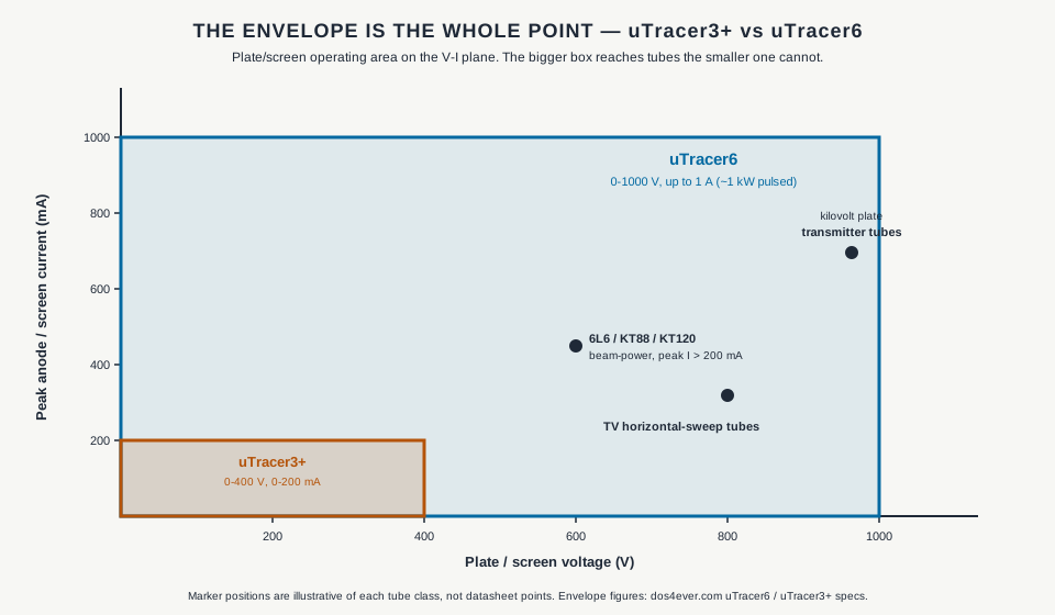
The uTracer6 is Ronald Dekker’s kilovolt-class DIY tube curve tracer — a through-hole kit sold from dos4ever.com that sweeps a vacuum tube’s full plate/screen characteristic over a 0–1000 V, up to 1 A envelope (roughly 1 kW of peak pulsed power), with grid bias from 0 to −100 V on the base board and 0 to +100 V plus grid-current measurement when the optional extension board is fitted. It does this without a kilowatt of continuous supply behind it, because it never applies that power continuously: it charges a reservoir capacitor to the target voltage, switches the charged cap onto the tube for a ~1 ms pulse, samples the current during that window, and lets go. That single trick — shared across the whole uTracer line — is what lets a 6×6-inch hobbyist board test transmitter and sweep tubes that would otherwise demand a bench full of high-voltage, high-dissipation supplies.
Two things this instrument is not — both of which it is commonly mistaken for, and both of which matter for reading everything that follows:
- It is not a revision of the uTracer3. The “6” is a model designation in Dekker’s line, not a PCB or firmware revision suffix bolted onto the uTracer3. It has its own construction weblog, its own larger board, its own high-voltage power stage, and its own price. Vol 2 walks the full lineage; the short form is uTracer3 (2012, 300 V) → uTracer3+ (2015, 400 V) → uTracer6 (~2019–2020, 1000 V / 1 A).
- It is not the current mainstream flagship. As of 2026 the mainstream audio-tube model in the line is the uTracer NXT (a ground-up new design that replaced the uTracer3+, roughly 450–500 V). The uTracer6 sells in parallel with the NXT as the deliberate high-voltage/high-current specialist “for experienced users.” It is also not a “successor to the eTracer” — the eTracer is an unrelated Essues/Taiwan product that arrived at the same pulsed-cap idea independently, covered in its own dive.
1.2 What a curve tracer is doing, and why the pulse matters here
A tube curve tracer answers the question a tube data sheet answers, but for your particular tube: for a given grid bias, how much plate current flows as plate voltage is swept, and how does that family of curves shift as the grid bias steps? Out of that you get transconductance (gₘ), plate resistance, the operating point, and — for matched-pair selection in a push-pull output stage — a direct comparison of two tubes’ curves under identical conditions. The primer for what an I-V curve is and how to read one lives in the hub’s Curve Tracers overview; this dive is about the instrument that produces those curves at kilovolt scale.
The obvious way to build a tracer is a big regulated DC plate supply and a way to sweep it. The problem is dissipation. A tube’s plate can only sink so much continuous power before the plate glows and the tube is damaged — but the interesting parts of its characteristic (high plate voltage and high plate current at once) sit well past that continuous limit. Trace those points with DC and you cook the tube; trace them for a millisecond and the tube’s thermal mass never notices. That is the entire argument for pulsed tracing, and it is why the whole uTracer line — the 3, the 3+, the 6, and the NXT — is built around it.
1.2.1 Charge the cap, then pulse
Dekker’s implementation, in his own framing, keeps the power electronics almost embarrassingly small. Each high-voltage rail is generated by a boost converter — “nothing more than an inductor, a transistor and a diode” — that charges a large electrolytic reservoir capacitor up to the voltage the current measurement point needs. When the point is taken:
- The converter charges the reservoir cap to the target plate/screen voltage.
- Every switch-mode converter is switched off, so nothing is injecting switching noise.
- An electronic high-voltage switch connects the charged cap to the tube for a brief pulse, on the order of 1 ms — a short stabilization interval, then the current is sampled.
- The pulse partially discharges the cap; that droop is measured and compensated in the reported result, so the number reflects the actual voltage across the tube during the sample rather than the pre-pulse cap voltage.
There is a protective escape hatch: if the current-compliance limit is exceeded during a pulse, the software can cut that pulse short to about 10 µs to protect the tube and the hardware. That 10 µs figure is a fast-abort, not the normal measurement window and — importantly for this dive — not evidence of “faster sampling.” The normal pulse is ~1 ms, the same order as the rest of the line; the uTracer6’s advance over the uTracer3+ is voltage and current headroom, not sample rate.
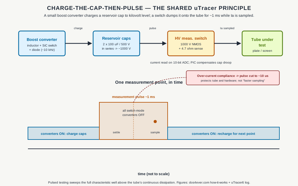
Vol 3 opens up the hardware behind that block diagram — the SiC boost switch, the 1000 V measurement NMOS and its gate driver, the DAC-driven grid rail, the PIC and its ADC. Here the point is only the shape of the technique, because it explains the instrument’s defining trade: enormous pulsed envelope, tiny continuous power, and a genuine kilovolt shock hazard living on those reservoir caps.
1.3 The distinct-model identity
This is the claim the whole dive is built to defend, because it is widely (and wrongly) described as a newer revision of the uTracer3: the uTracer6 is a separate instrument, a high-voltage model, not a newer revision of the uTracer3. The evidence is not subtle:
- Its own construction weblog. Dekker documents “The uTracer V6” in a dedicated build log distinct from the uTracer3 log — the same way each real model in his line gets its own log.
- Its own board. The uTracer6 PCB is 6 × 6 in (152.4 × 152.4 mm) — physically larger than the uTracer3/3+ board at 4 × 6.4 in (101.6 × 162.5 mm). It is not a drop-in replacement PCB.
- Its own high-voltage power stage. The boost switch is a silicon-carbide MOSFET (Vol 3) chosen for its 1700 V breakdown; the measurement switch is a 1000 V-rated NMOS; the grid bias is DAC-driven through a high-voltage op-amp on a dedicated negative rail rather than the uTracer3’s PWM-derived grid supply; the microcontroller is a PIC 16F884, a step up from the uTracer3’s PIC 16F874A. This is a ground-up high-voltage redesign, not a re-spin of an existing board.
- Its own price and place in the catalog. It is sold as its own kit, at its own price, alongside the mainstream tracer rather than replacing it.
Dekker positions it plainly: the uTracer6 is the tracer “for people demanding higher voltage and current to test special-purpose tubes … for more experienced users who really need the extended voltage and/or current ranges.” He pairs that with an honest warning — the higher-voltage, higher-current stage is more prone to oscillation than the uTracer3, which is exactly why he markets it to experienced builders rather than as the default first tracer. Vol 5 gets into oscillation mitigation on the bench; for now it is enough to note that the extended envelope is bought with a handling penalty, and Dekker says so up front.
1.3.1 Where “current generation” actually lands
It is worth being precise, because it is easy to over-correct. The uTracer6 is a current-production model — you can order one today — but it is not the line’s current mainstream flagship. That role belongs to the uTracer NXT, a completely new design that replaced the uTracer3+ for general audio-tube work and which, per Dekker, “incorporated learnings from the uTracer6 as well as work on the uTracer7.” So the accurate picture is two current models sold side by side: the NXT as the mainstream audio-tube tracer (roughly 450–500 V), and the uTracer6 as the parallel high-voltage/high-current specialist (1000 V / 1 A). When this dive says “distinct model, not the current generation,” that is the distinction it means. The NXT gets its own dive; Vol 6 draws the head-to-head on when to reach for which.
1.4 The envelope, in numbers
The reason the uTracer6 exists at all is the envelope. Against its immediate predecessor:
Table 1 — The reason the uTracer6 exists at all is the envelope. Against its immediate predecessor
| Parameter | uTracer6 | uTracer3+ |
|---|---|---|
| Anode (plate) voltage | 0 to 1000 V | 2 to 400 V |
| Screen (g2) voltage | 0 to 1000 V | 2 to 400 V |
| Anode / screen current | up to 1000 mA (~1 A) | 0 to 200 mA |
| Grid (g1) bias, negative | 0 to −100 V | −50 V to 0 V |
| Grid bias, positive | 0 to +100 V (extension board only) | not available |
| Grid current measurement | 0–100 mA (extension board only) | n/a |
| Peak pulsed output power | up to ~1 kW | ~80 W (400 V × 200 mA) |
| Heater supply | 0–19.5 V (PWM, MOSFET-driven) | 0–19.5 V, max 1.5 A |
| PCB size | 6 × 6 in (152.4 × 152.4 mm) | 4 × 6.4 in (101.6 × 162.5 mm) |
A few of these figures carry history worth flagging so nobody mis-cites them. The original uTracer3 (pre-2015) topped out at 0–300 V; the uTracer3+ raised that to 0–400 V from January 2015 — so “400 V” is specifically the 3+ ceiling, not the whole uTracer3 family’s. And early uTracer6 development notes floated an ~800 V / >500 mA design target; the shipping model settled at 1000 V / 1 A, so treat 800 V as a historical way-point, not the final spec. The grid-bias DAC resolves to about 3.1 mV per step (≈ 100 V / 2¹⁵) — fine enough to place a bias point precisely, which matters when you are reading gₘ off closely spaced curves.
1.4.1 What the extra headroom actually buys
Numbers on a page are abstract; the point is the tubes they reach. The uTracer3+ ceiling of 400 V / 200 mA simply cannot exercise a whole class of power tubes at their real operating points:
- Beam-power and sweep output tubes — 6L6, KT88, KT120 and relatives. In push-pull class-AB these routinely swing peak plate currents well above 200 mA, and their useful characteristics extend past 400 V on the plate. The uTracer3+ clips the curve exactly where it gets interesting for matched-pair selection in an amplifier output stage.
- TV horizontal-sweep tubes, which are specified at plate voltages beyond 400 V by their nature.
- Transmitter tubes, where the 1000 V rating is squarely aimed — plate voltages in the kilovolt range are the normal operating regime, not an edge case.
The uTracer6’s 1000 V / 1 A (≈1 kW pulsed) envelope covers those operating points where the uTracer3+ can only approach them. That is the confirmed, numeric reason this instrument earns bench space next to a tracer that already handles ordinary receiving and small-signal tubes. Vol 5 works actual sweep-tube and transmitter-tube sessions at the kilovolt envelope.
1.5 Why it’s on this bench
The tube-test workflow here is a triage-then-characterize pipeline, and the uTracer6 is firmly on the characterize end. Quick go/no-go triage — is the tube gassy, shorted, dead, or weak — is what the Heathkit TT-1 (mutual-conductance) and the Supreme 385 (emission) handle fast. The curve tracers come out when the question is quantitative: full transfer curves for a SPICE model, or tightly matched output-tube pairs for a push-pull stage. The bench keeps two pulsed-HV tracers for that — the commercial eTracer (Essues, 0–750 V / 300 mA) and this DIY uTracer6 — and the uTracer6’s specific edge is the kilovolt envelope: its 1000 V / 1 A ceiling reaches the beam-power, sweep, and transmitter tubes that neither the eTracer nor the uTracer3+ fully exercise. The price of that reach is the oscillation-proneness Dekker warns about, which is why it lives here as the specialist rather than the default.
One bench-discipline note that carries through every later volume: it is a genuine shock hazard. The
anode and screen reservoirs charge to about 1000 V, and a charged reservoir cap holds a lethal charge
whether or not a measurement is running. Treat the reservoir caps as live until proven dead with a meter,
observe discharge discipline, and read the safety material in Vol 5 and the hub’s
_shared/legal_ethics.md before first power-up. One-hand rule above
~50 V, always — and this box runs at twenty times that.
1.6 The decision frame: is this the right tracer to build?
Whether the uTracer6 is the right choice depends on three questions, and the honest answers steer some people to a different model in the same line:
- Do the tubes you care about actually need more than ~400 V or ~200 mA? If the answer is no — if the work is receiving tubes, small-signal audio, and ordinary output tubes at sane operating points — the mainstream uTracer NXT is the better buy: cheaper, newer, less oscillation-prone, and mainstream. The uTracer6’s headroom is dead weight if you never use it, and the extra handling care is a real tax. Vol 6 lays out the crossover explicitly.
- Are you comfortable building and living with a kilovolt kit? The uTracer6 is an all-through-hole kit — hobbyist-solderable, no fine-pitch surface-mount — so the assembly is amateur-friendly. But it is more oscillation-prone than the smaller tracers and it runs at genuinely dangerous voltages, and Dekker aims it at experienced builders for exactly those reasons. This is not a first-tracer project.
- Do you specifically want the sweep/beam-power and transmitter-tube reach? If yes — matched KT88/ KT120 pairs, TV sweep tubes, transmitter finals, published SPICE models at real operating points — then the uTracer6 is the tool in the line built for that, and nothing else in the uTracer catalog covers the full kilovolt envelope.
For this bench the answer to all three is yes, which is why the uTracer6 is here rather than a second NXT. What follows builds out the case: Vol 2 places it precisely in the uTracer lineage and explains why Dekker built a high-voltage model at all; Vol 3 opens the hardware; Vol 4 is the kit build and host software; Vol 5 is operating and keeping it running at the kilovolt envelope; Vol 6 is the cheatsheet and the head-to-head comparisons against the eTracer and the rest of the uTracer line.