uTracer6 · Volume 2
uTracer6 — Vol 2: The uTracer Line & Where the 6 Fits
uTracer3 → 3+ → NXT (mainstream), with the uTracer6 as the parallel kilovolt branch
2.1 The line, not the revision
The single most common mistake about this instrument is baked into its name. The “6” reads like a revision suffix — as if a uTracer3 grew up into a uTracer6 the way a Fluke 87 became an 87V. It did not. The uTracer6 is a distinct model in Ronald Dekker’s version line, a ground-up kilovolt-class redesign that sells in parallel with the mainstream tracer rather than replacing it. It has its own dedicated construction weblog (“The uTracer V6”), its own kit, its own price, its own larger PCB, and its own high-voltage power stage. Calling it “the latest uTracer3” gets both facts wrong at once: it is not a uTracer3, and it is not the latest anything.
This volume traces the family tree so the 6’s position is unambiguous. Two things fall out of that tree that matter for every later volume:
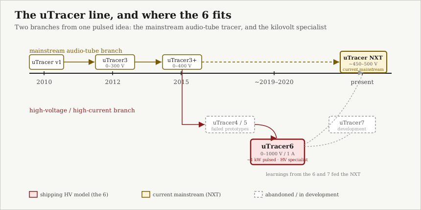
- The line has two branches from one idea: a mainstream audio-tube tracer that ran uTracer3 -> uTracer3+ -> uTracer NXT, and a high-voltage/high-current branch whose one shipping product is the uTracer6.
- The 6 is not the current generation. As of 2026 the current mainstream audio-tube model is the uTracer NXT, a ground-up new design that replaced the uTracer3+. The uTracer6 is the parallel specialist — the tool you reach for when the NXT (and the 3+ before it) runs out of voltage or current headroom.
2.2 Where it started: the pulsed idea (2010)
The whole line descends from one insight, conceived around Christmas 2010: you do not need a big continuous high-voltage supply to trace a tube’s characteristics. A continuous DC plate supply has to be sized for the tube’s continuous dissipation, which caps the envelope and forces bulky, expensive hardware. The pulsed approach sidesteps that. A small boost converter — Dekker describes it as “nothing more than an inductor, a transistor and a diode” — charges a large electrolytic reservoir capacitor up to the target voltage over time. For a measurement, that charged cap is switched onto the tube for a brief pulse while the anode and screen currents are sampled, then disconnected. Because the tube only sees the high voltage for roughly a millisecond at a time, you can sweep operating points well above the tube’s continuous plate-dissipation rating without cooking it.
That pulsed-cap-then-sample principle is the genetic material shared by every member of the line, from the original uTracer through the uTracer3, the uTracer6, and the uTracer NXT. It is what makes the family recognisably one family. The models differ in how high they charge the cap, how much current the switch can pass, how the grid is biased, and what microcontroller runs the show — but the measurement philosophy is constant. Vol 3 covers the 6’s implementation of it in detail; the point here is that the 6 did not invent a new method, it scaled an existing one up to the kilovolt regime.
2.3 The mainstream branch: uTracer3 → 3+ → NXT
2.3.1 uTracer3 (2012, 0–300 V)
The uTracer3 is where the idea became a shipping kit. The PCB was designed in 2012 and the first kits went out to customers that year. The original uTracer3 topped out at 0–300 V on the plate. This is the model most people mean when they say “a uTracer” — the mainstream, audio-tube-oriented tracer that made pulsed curve tracing cheap and accessible to hobbyists.
2.3.2 uTracer3+ (2015, 0–400 V)
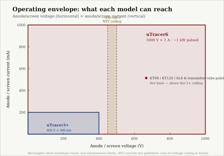
In January 2015 the uTracer3+ replaced the uTracer3, extending the plate/screen range from 0–300 V to 0–400 V. This is the direct predecessor against which the 6’s envelope is most usefully compared, because the 3+ was the standing mainstream model when the 6 was conceived. Its full envelope: plate and screen 2–400 V, anode/screen current 0–200 mA, grid bias −50 V to 0 V, heater 0–19.5 V at up to 1.5 A. Peak pulsed power works out to roughly 80 W (400 V × 200 mA). Those numbers are the ceiling the 6 was built to break through, and they recur throughout this dive as the baseline.
2.3.3 uTracer NXT (current mainstream, ~450–500 V)
The uTracer NXT is where the mainstream branch is today. It is not a 3+ revision either — it is a completely new, ground-up design that replaced the uTracer3+. Its plate range is roughly 450–500 V, a modest bump over the 3+, and it explicitly “incorporated learnings from the uTracer6 as well as work on the uTracer7.” So the relationship runs both ways: the 6 is a sibling of the mainstream branch, not a child of it, and some of what Dekker learned building the kilovolt specialist fed back into the mainstream tracer that now sits on most benches.
The practical takeaway for anyone deciding what to buy: if you are testing ordinary receiving and small audio tubes, the NXT is the mainstream answer, not the 6. The 6 earns its place only where the extra voltage and current are genuinely needed — and that is exactly how Dekker markets it. (Vol 6 lays out the reach-for-the-6-vs-the-NXT decision explicitly, with the eTracer as the third point of comparison.)
2.4 The HV branch: uTracer4/5 → uTracer6
2.4.1 Two prototypes that did not ship (uTracer4, uTracer5)
The path to a high-voltage tracer was not a straight line. The uTracer4 and uTracer5 are documented as failed / abandoned prototype iterations on the road to the kilovolt design. They never became shipping kits. Their significance here is negative but real: they are the reason the numbering jumps from the “3” family straight to a “6,” and they are evidence that the 6 was a hard, iterated engineering problem rather than a quick voltage bump. Pushing the pulsed method from 400 V to 1000 V, and from 200 mA to 1 A, meant a genuinely different power stage and switch technology — two prototype generations’ worth of difficulty.
2.4.2 uTracer6 (~2019–2020, 0–1000 V / 1 A)
The uTracer6 is the shipping product of that HV branch. Forum discussion of its target specs dates to January 2020, and the model was developed and released in roughly the 2019–2020 window. (The exact release month is not firmly documented, so treat the year as approximate.) One historical note worth keeping straight: early development cited an ~800 V / >500 mA design target, but the shipping model settled higher, at 1000 V / 1 A on both anode and screen. Treat the 800 V figure as an abandoned target, not a spec.
The shipping envelope jumps to 0–1000 V and up to ~1 A on both anode and screen (≈1 kW pulsed), with grid bias to −100 V (0 to +100 V and grid-current measurement via the uTracer6-only positive-grid extension board). Vol 1 carries the full parameter-by-parameter envelope table and its side-by-side comparison against the 3+; it is not repeated here.
What makes this a distinct model rather than a re-spin of the 3+ is that the hardware behind those numbers was redesigned end to end for the kilovolt regime — a silicon-carbide boost switch, a 1000 V HV measurement switch, DAC-driven grid bias through an LTC6090 on a negative rail, a PIC16F884 in place of the uTracer3’s PIC16F874A, and a physically larger 6 × 6 in through-hole board that is not a drop-in replacement. Vol 1 enumerates that distinct-model part list and Vol 3 dissects the architecture; the lineage point here is simply that essentially nothing in the power path carried over unchanged. This is a new instrument that happens to share a measurement philosophy and a host GUI with its mainstream cousins.
2.4.3 uTracer7 (in development)
Beyond the 6, the uTracer7 is a further development effort documented in its own V7 weblog. It has not shipped as a mainstream product; its role in the story is that its work, together with the 6’s, fed the uTracer NXT. It is included here only so the family tree is complete — the 6 is not the end of the line, but the 7 is not a replacement for the 6 either.
2.5 Why a 1000 V specialist has to exist
The envelope numbers are not abstract. The reason the HV branch exists at all is that a large and interesting class of tubes lives above the mainstream ceiling, and the pulsed method makes reaching them affordable in a way a continuous kilovolt supply never could.
A large and interesting class of tubes — beam-power and sweep tubes (the 6L6 / KT88 / KT120 family, TV horizontal-sweep tubes) and transmitter tubes — lives above the 3+‘s 400 V / 200 mA ceiling, and the uTracer6’s 1000 V / 1 A (≈1 kW pulsed) envelope reaches operating points on all of them that the 3+ cannot. Vol 1 works that headroom argument out tube-by-tube against the envelope chart. For the lineage story the point is only this: that need is what forked the family into a second branch instead of being met by stretching the mainstream tracer, and the advance is more headroom — higher voltage and higher peak current — not “faster” and not “newer.”
Two guardrails on how far to push that framing:
- The 6’s advance is envelope, not speed. There is no source indicating a faster sample rate; the measurement pulse is still on the order of ~1 ms (with a ~10 µs fast-abort when the current-compliance limit is exceeded, to protect the tube and hardware), the same order as the rest of the line. Anyone who describes the 6 as “faster sampling” is describing something that does not exist.
- The headroom comes with a stated cost: Dekker positions the 6 as a tool “for people demanding higher voltage and current to test special purpose tubes… for more experienced users who really need the extended voltage and/or current ranges,” specifically because the higher-voltage/current stage is more prone to oscillation than the mainstream tracer. It is deliberately not marketed as a first tracer. Vol 5 covers the oscillation-proneness and its mitigation in operating detail.
2.6 What the 6 shares with its cousins, and what it does not
It helps to be precise about which family traits carried over and which were redesigned, because the shared traits are what make the 6 feel familiar and the redesigned ones are what make it a distinct model.
Shared across the line:
- The pulsed measurement principle — charge a reservoir cap, pulse it onto the tube for ~1 ms, sample during the window, switch-mode converters off during the pulse, then compensate the measured result for the cap’s droop during the pulse.
- Firmware lineage: the PIC16F884 firmware remains compatible with the uTracer3 lineage.
- The host software family: the same Windows Visual-Basic GUI serves the uTracer3 and the uTracer6, saving data to
.utdfiles and plots to.bmp(Vol 4 covers the software in full). - The through-hole, hobbyist-solderable, kit-of-parts DIY nature.
Redesigned for the 6: the entire HV power path, the grid-bias circuit, the microcontroller, and the physical board were all rebuilt for the kilovolt regime — the specific part numbers live in Vol 1’s distinct-model list and the shipping-envelope summary above, and Vol 3 dissects the circuitry. The one lineage-unique item worth naming here is the optional positive-grid extension board (+100 V grid, 0–100 mA grid-current measurement), which exists only for the 6 and has no counterpart in the mainstream line.
That split is the whole thesis of this volume: a shared measurement soul, a rebuilt high-voltage body. The 6 is a Dekker uTracer through and through — and just as clearly, it is not a uTracer3 with a bigger number.
2.7 Placing the 6 on Jeff’s bench
For this project specifically, the lineage settles which questions the 6 answers and which it does not. The mainstream branch (a NXT, or a 3+) would be the tool for ordinary receiving and small-signal audio tubes. The 6 is on the bench for the top of the range — the sweep/beam-power output tubes and transmitter tubes whose curves the 3+ / NXT cannot fully draw — and it earns that slot precisely because it is the parallel high-voltage specialist, not the everyday tracer. It shares the bench with the commercial eTracer (an unrelated Essues product that arrived at the same pulsed idea independently — not part of this line and never a “predecessor” the 6 succeeded); that head-to-head, and the 6-vs-NXT choice, are the subject of Vol 6.