uTracer6 · Volume 4
uTracer6 — Vol 4: Building the Kit & Host Software
The through-hole kit, the positive-grid extension, calibration, and the VB GUI
4.1 Scope of this volume
The uTracer6 is not a boxed instrument you unpack and switch on. It is a kit — Ronald Dekker sells the kilovolt-class tracer as a bag of through-hole parts, a bare PCB, a pre-programmed microcontroller, and a printed manual, and it is your soldering iron that turns that into a working curve tracer. This volume covers that half of ownership: what actually arrives in the box, what does not, the optional positive-grid extension board that only the “6” can use, the assembly and the single warm-up-and-trim calibration step that stands between a stuffed board and trustworthy data, and the Windows host software that drives it — the same Visual Basic GUI family that has driven the whole uTracer line, plus what it writes to disk and where the SPICE-modelling workflow really sits.
The electrical envelope, the boost-converter HV stage, and the part-by-part architecture belong to Vol 3; operating the finished instrument, the sweep-tube and transmitter-tube work at the kilovolt envelope, and the safety discipline around the charged reservoir capacitors belong to Vol 5. Here the tube is mostly not in the socket. This is the build bench and the laptop, not the high-voltage measurement.
One frame to carry through everything below: the uTracer6 is a distinct high-voltage model in Dekker’s line — a ground-up 0-1000 V / 1 A design — not a revision of the uTracer3, and not the line’s current mainstream (that role belongs to the uTracer NXT; see Vol 2). Its kit price, its board, and its extension option are all its own.
4.2 What ships in the box
The uTracer6 (the 1000 V version) kit is EUR 329, or EUR 350 paid via PayPal, with worldwide shipment by national post included in that price. For that you get:
- All the electronic components for the board.
- The pre-programmed PIC controller — the PIC 16F884 arrives already flashed with the uTracer firmware, so there is no separate programming step and no need to own a PIC programmer.
- The PCB — the 6 x 6 in (152.4 x 152.4 mm) through-hole board.
- A printed construction manual.
That is a genuinely complete electronics kit: every resistor, capacitor, semiconductor, inductor, and connector for the board is in the bag, the controller is flashed, and you build from a paper manual rather than hunting a BOM.
What is not in the box matters just as much, because it is the difference between “kit arrived” and “instrument on the bench”:
- Tube sockets — you choose and supply the sockets for the tube families you intend to test.
- Selector switches — the front-panel switching is yours to specify and wire.
- The power cord.
In other words the kit is the measurement engine; the human-interface and mains-entry hardware around it — sockets, switches, cord, and whatever enclosure you build — is a bring-your-own exercise. Budget for it, and budget bench time for it, because wiring sockets and selector switches to the board is a real part of the build, not an afterthought.
4.2.1 Price in context
For a sense of where EUR 329 sits: the current-mainstream uTracer NXT kit is EUR 239 (EUR 255 via PayPal). The uTracer6 costs more not because it is newer — it is not the current generation — but because it is the high-voltage/high-current specialist, with a larger board and a heavier HV power stage. You are paying for the kilovolt envelope, not for a revision bump.
4.3 The positive-grid extension board
The uTracer6 is the only model in the line that accepts the positive-grid extension board, and it is a separate purchase: EUR 80, or EUR 85 via PayPal, again with worldwide regular-mail shipping included. Like the main kit it ships as a PCB plus all its components.
What it adds, and why it only exists for the “6”:
- Positive grid bias, 0 to +100 V. The base uTracer6 already reaches 0 to -100 V of (negative) grid-1 bias. The extension lifts the grid positive, up to +100 V, so you can drive tubes into positive-grid operating regions that the negative-only base configuration cannot reach.
- Grid-current measurement, 0-100 mA. Once the grid goes positive it starts drawing current, and characterising a tube in that region is meaningless unless you can measure that grid current — so the extension board also brings a 0-100 mA grid-current measurement path.
This is a uTracer6-only capability. The uTracer3+ has no positive-grid path at all (its grid range is -50 V to 0 V), and this extension board works only with the uTracer6. If your target tubes are conventional audio and receiving types run with negative grid bias, you may never fit it. If you are chasing transmitter tubes, certain sweep applications, or any device you want to characterise with grid current flowing, it is the reason to own the “6” over anything else in the line.
4.4 Building it
The uTracer6 is all through-hole construction — Dekker describes the parts as amateur-friendly, and there is no surface-mount work to do. That is a deliberate choice for a kilovolt-class DIY instrument: through-hole parts are hand-solderable with an ordinary iron, inspectable by eye, and forgiving to rework, which matters on a board that will carry ~1000 V rails.
Practical notes for the build, all consistent with the kit as delivered:
- You are building onto a 6 x 6 in (152.4 x 152.4 mm) board. This is physically larger than the uTracer3/3+ board (4 x 6.4 in / 101.6 x 162.5 mm) — it is not a drop-in replacement for a uTracer3 and it is not the same layout. Plan your enclosure and panel around the 6 x 6 in footprint.
- The PIC is pre-programmed, so the microcontroller goes in ready to run — no bootloader dance, no programmer.
- The high-voltage section is real. Even during construction, remember what this board becomes: two 100 µF / 500 V electrolytics in series (a ~1000 V-rated reservoir) that charge toward ~1000 V and can deliver ~1 kW peak pulsed power. The stored-energy figure and the safety discipline that follows from it are a Vol 5 operating concern, but it shapes the build too — solder joints on the HV rails, the reservoir caps, and the HV switch have to be clean and well-formed, because there is no margin for a cold joint or a solder whisker at a kilovolt.
- You supply and wire the sockets, selector switches, and cord. This is where most of the mechanical build time goes: laying out a panel, mounting sockets for the tube families you care about, wiring the selector switching to the board, and bringing in mains through your own cord.
The build produces a bench instrument you then calibrate (below) before it produces trustworthy curves.
4.5 Calibration: warm up, then null the grid zero
There is one calibration step you cannot skip, and it is specifically about the grid bias. The uTracer6 generates its grid bias differently from the uTracer3 — it is DAC-driven through a high-voltage op-amp rather than PWM-derived (Vol 3) — and that circuit has a small offset that must be trimmed to zero with a potentiometer.
The procedure, in order:
- Power the instrument up and let it warm for about 20 minutes before touching the calibration. The analog rails need to reach thermal equilibrium; trimming a cold board just means re-trimming a warm one.
- Trim the grid-zero potentiometer so the grid-bias offset sits at true 0 V.
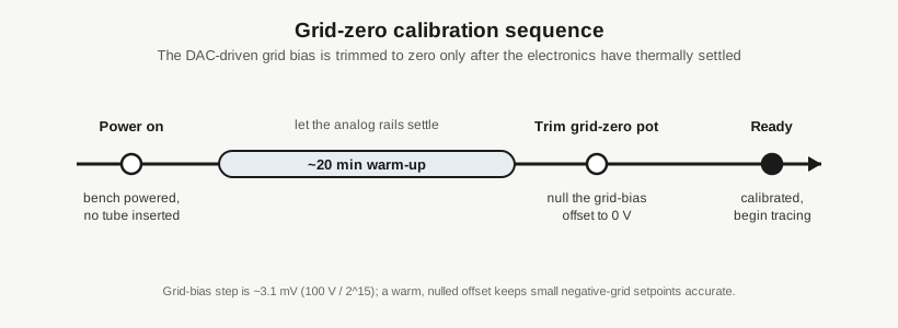
Why this matters enough to be the one mandatory trim: the grid-bias DAC step is about 3.1 mV (100 V spread over 2^15 counts). Small negative-grid setpoints — exactly the region where a tube’s transfer characteristic is steepest and where a curve tracer earns its keep — are only as accurate as the zero they are referenced to. A warm, nulled offset keeps those small Vg values honest. Trim it cold, or skip the warm-up, and every low-bias curve inherits that offset.
4.6 The host software: the Visual Basic GUI
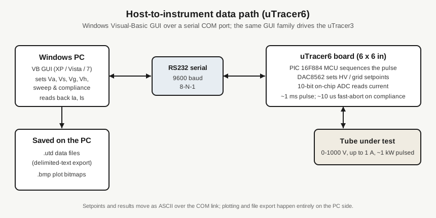
The uTracer6 is driven from a Windows PC by a Visual Basic GUI, the same host-software family that serves the uTracer3. There is no on-instrument display doing the work; the PC sets every operating point, sequences the sweep, and reads the results back.
- Connection: a serial COM port. The link runs at 9600 baud, 8-N-1 (Vol 3). On a modern laptop with no native serial port, that means a USB-to-serial adapter.
- Documented OS support: Windows XP, Vista, and Windows 7. Community reports have it running on later Windows too, but the officially documented compatibility list is XP / Vista / 7 — treat anything beyond that as “reported working,” not guaranteed.
- What the GUI does: you set the anode/screen voltages, the grid bias, the heater voltage, the sweep definition, and the current-compliance limit in the GUI; the instrument runs the pulsed measurement and returns the sampled anode and screen currents for plotting.
4.6.1 Data output: .utd files and delimited-text export
Measurements save to .utd (uTracer data) files. The GUI can lay the data out in several formats:
- An 8-column measurement matrix — point number, curve number, Ia and Is (in mA), Vg, Va, Vs, and Vh. This is the raw per-point table.
- A “block” format — the X-axis variable in the first column, with each swept curve in the following columns. This is the shape you want for handing curve families to a plotting or analysis tool.
- A “list” format.
There is an “Add Text” tick-box in the export. Leave it ticked and the file carries human-readable annotation; untick it and the GUI emits a data-only, delimited file — effectively CSV/TSV-style text — suitable for importing into other applications. It is worth being precise about the extension here: the file is still written as .utd, not .csv, but with “Add Text” off its contents are plain delimited numbers you can open or import anywhere. So “delimited-text export” is real and built in; it is just not a separate .csv menu item.
4.6.2 Plots: .bmp only
Graphs export as bitmap (.bmp) images only. That is a stated limitation of the Visual Basic implementation, not a preference — there is no vector or PNG plot export. If you need a publication-quality or vector plot, the practical route is to take the delimited .utd data (Add Text off) into your own plotting tool rather than to lean on the GUI’s bitmap.
4.6.3 SPICE modelling is a documented workflow, not a button
The manual includes a “Spice Modelling” section, and modelling tube behaviour from uTracer6 curves is very much part of what the instrument is for. But be clear about what the GUI does and does not do: it does not appear to auto-extract or one-click-export a ready-made SPICE model file. SPICE modelling with the uTracer6 is a documented workflow — you capture the curves, then fit a tube model from that data following the manual’s method — rather than an automated export. Anyone expecting to press a button and receive a .lib model will be disappointed; anyone willing to follow the modelling procedure has everything they need. (Whether a newer build has added automated model export is undocumented; treat automated SPICE export as unverified.)
4.6.4 Third-party host software: utMax
The Dekker GUI is not the only option. A third-party host application, utMax (from Black Magic Amplifiers), supports the uTracer 3 and uTracer 6. It is worth knowing it exists if the stock VB GUI’s workflow or its bitmap-only plotting does not suit you; it is an alternative front end for the same instrument, not a firmware change.
4.7 What you actually have to decide before ordering
Pulling the build-side choices together, before money changes hands:
- Base kit, EUR 329 (EUR 350 PayPal) — non-optional; this is the instrument.
- Positive-grid extension, +EUR 80 (EUR 85 PayPal) — optional, uTracer6-only. Fit it if you want +100 V grid bias and 0-100 mA grid-current measurement (transmitter tubes, positive-grid characterisation). Skip it for conventional negative-grid audio/receiving work.
- Sockets, selector switches, power cord, enclosure — all yours to source and build. Not in either kit.
- A PC with a serial COM port (or a USB-serial adapter) running Windows — XP/Vista/7 is the documented target; the VB GUI is how you drive the instrument at all.
None of these are hard calls, but they are all your calls — which is the nature of a DIY kilovolt tracer. The kit gives you a complete, pre-programmed measurement engine; the sockets you choose, the panel you wire, the warm-up-and-trim you perform, and the host PC you connect are what make it your instrument. Vol 5 picks up from a calibrated, connected uTracer6 and puts tubes in the socket.