uTracer6 · Volume 5
uTracer6 — Vol 5: Operating & Keeping It Running
Sweep tubes at a kilovolt, oscillation, and ~12.5 J of stored energy per cap
5.1 Where this volume sits
Vols 1—4 covered what the uTracer6 is (a distinct Dekker kilovolt-class model, 0—1000 V and up to 1 A on both anode and screen, ~1 kW peak pulsed — not a uTracer3 revision, not the line’s current mainstream, which is the NXT), where it fits in the line, the hardware architecture, and the kit build plus host software. This volume is the bench-side manual: what a working session looks like, how the kilovolt envelope earns its keep on sweep and beam-power tubes, why the instrument oscillates when a smaller uTracer would not, and — the part that gets people hurt — how to live with the stored energy in the reservoir capacitors.
Everything below traces to Dekker’s construction weblogs and product pages on dos4ever.com, chiefly the uTracer6 construction log. Where a number is derived rather than quoted (the stored-energy arithmetic), it is called out as derived.
5.2 The pulsed measurement, from the operator’s chair
The uTracer6 does not sit a continuous DC supply on the plate. It uses the pulsed technique detailed in Vol 3’s architecture treatment and shared across the whole uTracer line; here it is framed from the operator’s chair rather than re-derived. Small boost converters — “nothing more than an inductor, a transistor and a diode” — charge large electrolytic reservoir capacitors up to the target high voltage, then an electronic switch connects that charged cap onto the tube for a brief pulse while the anode and screen currents are sampled. All the switch-mode converters are switched OFF during the measurement pulse, so the tube sees a quiet, stiff cap rather than a running switcher. The pulse partially discharges the cap; that droop is measured and compensated in the reported result.
The measurement pulse is on the order of ~1 ms — a short stabilisation interval and then the sample. It is not tens of microseconds, and the uTracer6 is not “faster sampling” than the uTracer3; the measurement window is the same order of magnitude. The advance of the 6 is voltage and current headroom (400 V to 1000 V, 200 mA to 1 A, grid to +/-100 V), not speed. If the current-compliance limit you set is exceeded, the software cuts the pulse short to about ~10 us to protect both the tube and the hardware. That fast-abort is your friend the first time you point a kilovolt at an unknown tube.
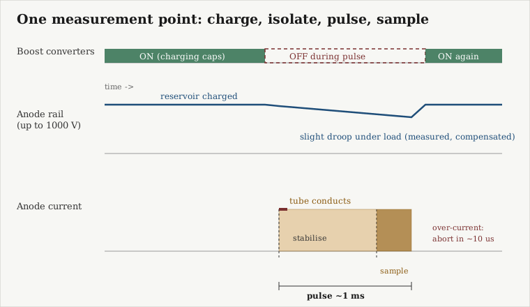
The practical consequence at the bench: a full curve family is a sequence of these charge-isolate-pulse-sample cycles, one per point, stepping the anode/screen setpoint along each curve and the grid bias between curves. Because the tube only ever sees ~1 ms bursts, the uTracer6 can sweep operating points well above the tube’s continuous plate dissipation without cooking it — that is the entire reason the pulsed architecture exists, and it is what makes a 1 kW pulsed envelope tractable from a small through-hole board.
5.3 A normal session: warm-up, calibration, first curves
Warm-up and grid-zero calibration. The grid-bias zero/offset is set with a potentiometer, and it is set after about ~20 minutes of warm-up, before the zero-grid-voltage calibration. Skipping the warm-up means the grid-bias offset you trim will drift as the analog front end settles, and on a tube whose interesting region is a few volts of grid bias wide that offset is the difference between a believable curve and a shifted one. The grid bias itself is DAC-driven through the high-voltage op-amp (an LTC6090 on a -85 V rail), giving a bias step of about ~3.1 mV (100 V / 2^15) — fine enough that the zero-offset trim genuinely matters.
The host link. The board talks to the Windows Visual-Basic GUI over a serial COM port, 9600 baud, 8-N-1. It is the same GUI family that serves the uTracer3. You set heater voltage, the anode and screen sweep ranges, the grid steps, and the current-compliance limit in the GUI; the PIC16F884 runs the pulse sequence and streams back the sampled points.
Heater first. The heater supply is 0—19.5 V, PWM-driven (around 1.22 kHz through a MOSFET). Set the correct heater voltage for the tube and let the cathode come up before you start pulsing the plate. For an unknown or suspect tube, see the gas/short caution below before you ever apply anode voltage.
Compliance is not optional. Set the current-compliance limit deliberately for every tube. The ~10 us fast-abort only helps if the limit is set somewhere sane; it is the mechanism that saves a tube (and the HV switch) when a point draws more than you expected. On the kilovolt ranges the energy behind that pulse is real, so treat the compliance number as a safety setting, not a convenience.
Reading the result. Points come back as an 8-column matrix (point #, curve #, Ia, Is in mA, Vg, Va, Vs, Vh) and save to .utd. Plots export as .bmp only — a stated Visual Basic limitation. Data-only delimited export is available by unchecking the “Add Text” box, which is how you get curves into another tool for modelling (SPICE modelling is a documented workflow here, not a one-click export — see Vol 4).
5.4 Sweep tubes and beam-power tubes at the kilovolt envelope
This is the reason the uTracer6 is on the bench rather than a uTracer3+ or an NXT. The 3+ caps at 400 V / 200 mA; the beam-power and sweep tubes that matter to an amplifier builder routinely need more of both.
- 6L6 / KT88 / KT120 family. In push-pull class-AB these tubes swing peak plate currents well above 200 mA, and their interesting operating points sit above 400 V. The uTracer3+ simply cannot reach the corner of the characteristic where a KT88 or KT120 actually lives at full song. The uTracer6’s 1000 V / 1 A envelope covers it, which is what lets you trace the real transfer curves you would use for matched-pair selection or a published tube model.
- TV horizontal-sweep tubes. These want plate voltages above 400 V by design. They are squarely inside the 6’s envelope and squarely outside the 3+‘s.
The peak pulsed power of ~1 kW (1000 V x 1 A) is what makes those operating points measurable without a continuous kilowatt supply — again, because the tube only sees the ~1 ms pulse.
A note on the positive-grid extension board (Vol 4): beam-power and transmitter tubes driven into grid current need the +100 V grid range and the 0—100 mA grid-current measurement that only the uTracer6 (with that add-on) provides. If your characterisation work touches grid-current regions, that board is not optional.
5.5 Transmitter tubes at the top of the range
The 1000 V ceiling is aimed beyond typical audio use, at high-power and transmitter tubes. The same pulsed architecture applies: you are sampling ~1 ms operating points, not running the tube continuously, so a transmitter tube can be swept toward operating points a bench supply could not hold. Two cautions specific to this end of the range:
- The stored energy behind a 1000 V pulse is at its maximum here (see the safety section). Everything about discharge discipline matters most when you are working transmitter tubes.
- Oscillation-proneness (next section) is worst with high-transconductance, high-power tubes and long leads. The transmitter-tube end of the envelope is exactly where the uTracer6’s “for experienced users” positioning is earned.
5.6 Oscillation: why the 6 does it and how to keep it quiet
Dekker frames the uTracer6 explicitly as an instrument for experienced users because the higher-voltage/current stage is more prone to oscillation than the uTracer3. This is a documented characteristic of the model, not a defect in a given unit. A tube plus its sockets plus the HV switch and sense resistor form a fast, high-gain loop, and at kilovolt levels with a hot beam-power or transmitter tube the loop can break into oscillation during the pulse.
Practical mitigation that follows from the architecture and from general HV-tube-test practice:
- Keep leads short and dressed. Long, loosely routed leads between the board, the sockets, and the tube add inductance to the loop. Short, direct wiring to the tube socket is the first defence.
- Grid stopper. A small resistor right at the grid pin is the classic anti-oscillation measure for high-transconductance tubes and applies here as much as in an amplifier. Put it at the socket, not back at the board.
- Watch the current trace, not just the plotted curve. Oscillation shows up as points that are noisy, non-monotonic, or that trip the compliance abort where a quiet tube would not. If a specific tube family always misbehaves, suspect the loop before you suspect the tube.
- Respect the model’s positioning. If you mostly test audio small-signal and rectifier tubes and rarely need above 400 V, the uTracer6 is the wrong tool and the NXT (Vol 2, Vol 6) is quieter and cheaper. Reach for the 6 when you actually need the kilovolt/amp headroom.
5.7 Unknown-tube caution: gas/short test first
Dekker’s own recommendation on the uTracer6 construction log: before subjecting an unknown tube to the uTracer6, do a gas/short test on a robust conventional tester first. A shorted or gassy tube presented to a kilovolt reservoir is a bad first meeting. On this bench that first-pass triage is exactly what the Heathkit TT-1 (dynamic Gm) and the Supreme 385 (emission, shorts/gas) are for — quick go/no-go and shorts detection on a rugged tester that will not be hurt by a bad tube. Only once a tube passes shorts/gas does it earn a pulsed sweep on the uTracer6. Treat that ordering as a rule, not a suggestion, and set a conservative current-compliance limit on the first sweep of anything you have not traced before.
5.8 Safety: ~12.5 J per capacitor, and it stays there after power-off
This is the part of the volume that is not optional reading. The uTracer6 charges its anode and screen reservoirs to about 1000 V, with peak pulsed power around 1 kW. Charged reservoir capacitors hold a lethal charge, and they hold it after you switch the instrument off. This is a genuine shock hazard — kilovolt class.
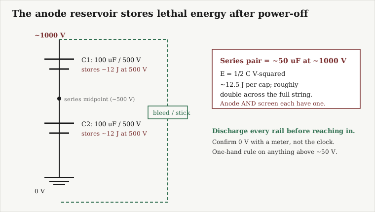
The stored energy, derived. The anode reservoir is two 100 uF / 500 V electrolytics in series to make the ~1000 V rail. The energy in a capacitor is E = 1/2 C V-squared. Each 100 uF cap charged to its 500 V working point stores 1/2 x 100e-6 x 500^2 = ~12.5 J. The two in series (about 50 uF effective at ~1000 V) hold roughly ~25 J between them: 1/2 x 50e-6 x 1000^2 = ~25 J. And the screen rail has its own reservoir of the same construction, so the bench total is higher still. (The capacitor values and topology are from Dekker’s construction log; the joule figures are derived from them.)
For scale: a few joules across the chest can kill. Twelve joules per capacitor, sitting on a 500 V section, with the full string at ~1000 V, is not a “respect it” hazard — it is a “assume it will hurt you until you have proven otherwise with a meter” hazard.
Discharge discipline (the bench rules that apply here).
- Bleed B+ before reaching in. Discharge every reservoir rail — anode and screen — with a proper discharge stick/bleed, not a screwdriver across the terminals.
- Confirm zero with a meter, not the clock. A bleed resistor can be open; a switch can lie. Prove each rail is at 0 V with a meter before your hand goes near it. Do not trust “I turned it off a minute ago.”
- One-hand rule on anything above ~50 V. Keep the other hand in your pocket or behind your back so a shock cannot cross your chest. This is the hub bench-discipline rule and it is not negotiable at kilovolt levels.
- Respect kV-rated probes. If you scope anything in the HV path, use a probe rated for it.
- Discharge before you unplug a tube. The reservoir does not know the tube is out. Same rule as reaching into the board.
Every one of these follows from a single fact: the energy that makes the uTracer6 able to pulse a transmitter tube is the same energy that is waiting in the caps after you flip the switch off.
5.9 Troubleshooting and keeping calibration
- Grid-zero drift. If curves look shifted along the grid axis, re-run the grid-zero calibration after a full ~20-minute warm-up. The ~3.1 mV bias step is fine enough that a stale offset trim is visible in the data. This is the routine maintenance calibration for the instrument.
- Noisy or non-monotonic points. Suspect oscillation first (see above), especially on high-gm or high-power tubes. Short the leads, add a grid stopper at the socket, and re-run before concluding the tube is bad.
- Compliance aborts where you did not expect them. Either the tube is drawing more than you think (check with a smaller, safer sweep), or the loop is oscillating and tripping the abort. The ~10 us fast-abort firing is information, not just a nuisance — read it.
- Serial link problems. The link is plain RS232 at 9600 8-N-1 over a COM port. A USB-serial adapter that enumerates as the wrong COM port, or a driver that does not present a real COM port, is the usual culprit; the protocol itself is unremarkable.
- Suspect a tube, not the tracer. When a single tube family always misbehaves and everything else traces cleanly, the tracer is fine — work the tube/loop, and re-triage the tube on the TT-1/Supreme 385 for shorts and gas.
5.10 Session checklist (logbook form)
- Bench clear, discharge stick within reach, meter on the HV range.
- Tube already passed shorts/gas on the TT-1 or Supreme 385 — if not, do that first.
- Set heater voltage; power up; warm up ~20 min; run grid-zero calibration.
- Enter anode/screen sweep ranges, grid steps, and a deliberate current-compliance limit in the GUI.
- Run the sweep — each point is charge/isolate/~1 ms pulse/sample; watch for compliance aborts and noisy points.
- Save
.utd; export delimited data-only if the curves are going to a modelling tool; plots to.bmp. - Power off, then discharge anode AND screen rails and confirm 0 V with the meter before touching anything — ~12.5 J per cap does not leave on its own.
- Log tube, settings, and any oscillation/compliance behaviour for next time.
Vol 6 turns this into a one-page cheatsheet and sets the uTracer6 against the eTracer and the uTracer3+/NXT so the “reach for the 6 or the NXT?” decision is quick.