uTracer6 · Volume 6
uTracer6 — Vol 6: Cheatsheet + Comparisons
Quick reference, vs the eTracer, and vs the uTracer3+/NXT lineage
6.1 Scope of this volume
The five volumes ahead of this one built the instrument up from principle: what the uTracer6 is (Vol 1), where it sits in Dekker’s version line (Vol 2), how the hardware and the pulsed measurement work (Vol 3), how the kit and the host software go together (Vol 4), and how to operate and maintain it at the kilovolt envelope (Vol 5). This last volume is the bench card you keep next to the tracer — a condensed spec and workflow reference — followed by the two comparisons that actually decide which box you power up: the uTracer6 against the commercial eTracer that shares its bench, and against its own lineage, the uTracer3+ it out-ranges and the uTracer NXT that is the current mainstream audio-tube model.
One thing to keep straight, because the model designation invites the error: the uTracer6 is a distinct kilovolt-class model in Dekker’s line, not a revision of the uTracer3, and not the “current generation.” The 1000 V / 1 A envelope is the whole point of the model; it is a parallel high-voltage specialist that sells alongside the NXT, not a successor that replaced anything. It is a DIY through-hole kit. The measurement pulse is roughly 1 ms — the model’s advance over the uTracer3+ is voltage and current headroom, not sampling speed.
6.2 Quick-reference cheatsheet
6.2.1 Electrical envelope
Table 1 — Electrical envelope
| Parameter | uTracer6 |
|---|---|
| Anode (plate) voltage | 0 to 1000 V (approx. 2-1000 V usable) |
| Screen (g2) voltage | 0 to 1000 V |
| Anode / screen current | up to 1000 mA (approx. 1 A) |
| Peak pulsed output power | up to approx. 1 kW |
| Grid (g1) bias, negative | 0 to -100 V |
| Grid bias, positive | 0 to +100 V (positive-grid extension board only) |
| Grid-current measurement | 0-100 mA (extension board only) |
| Grid-bias DAC step | approx. 3.1 mV (100 V / 2^15) |
| Heater supply | 0-19.5 V, PWM, MOSFET-driven |
| Measurement pulse | approx. 1 ms (approx. 1 ms stabilise, then sample) |
| Fast-abort on over-current | pulse cut to approx. 10 microseconds when the compliance limit trips |
6.2.2 Core hardware at a glance
Table 2 — Core hardware at a glance
| Block | Part / value |
|---|---|
| Microcontroller | Microchip PIC 16F884 |
| Host link | RS232, 9600 baud, 8-N-1 |
| Setpoint DAC | DAC8562, dual 16-bit |
| Measurement ADC | 10-bit, on-chip PIC ADC |
| HV boost switch | SiC MOSFET SCT2750NY (1700 V, 0.75 ohm), approx. 10 kHz |
| Reservoir capacitors | two 100 microfarad / 500 V electrolytics in series (approx. 1000 V) |
| HV measurement switch | NMOS FQD2N100 (or STD2NK100Z), 1000 V, IR25600 gate driver |
| Current-sense resistor | 4.7 ohm (default) |
| Grid-bias amplifier | LTC6090 HV op-amp on a -85 V rail, DAC-driven |
| Heater drive | MOSFET IPD048N06L3, PWM at approx. 1.22 kHz |
| Construction | all through-hole |
| PCB size | 6 x 6 in (152.4 x 152.4 mm) |
6.2.3 Kit and options
Table 3 — Kit and options
| Item | Price |
|---|---|
| uTracer6 kit (1000 V), incl. worldwide post | EUR 329 (EUR 350 via PayPal) |
| Positive-grid extension board (uTracer6-only) | EUR 80 (EUR 85 via PayPal) |
| Not included in the kit | tube sockets, selector switches, power cord |
The kit does include all the electronic components, the pre-programmed PIC controller, the PCB, and a printed construction manual. The extension board ships as its own PCB plus components and works only with the uTracer6.
6.2.4 Host software and data
- Windows host GUI written in Visual Basic; the same GUI family serves the uTracer3 and the uTracer6. Connects over a serial COM port. Documented for Windows XP / Vista / 7 (later Windows runs it per community reports).
- Measurements save to
.utdfiles. Export layouts include an 8-column matrix (point #, curve #, Ia, Is in mA, Vg, Va, Vs, Vh), a “block” format, and a “list” format. Un-ticking “Add Text” emits data-only delimited text for import elsewhere — effectively CSV/TSV, though the extension stays.utd. - Plots export as bitmap (
.bmp) only — a stated Visual Basic limitation. - SPICE modelling is a documented manual workflow, not a one-click export.
- A third-party host, utMax (Black Magic Amplifiers), also drives the uTracer 3 / 6.
6.2.5 Operating workflow, condensed
- Discharge discipline first. The reservoir caps hold a lethal charge at approx. 1000 V; confirm the rails are bled before reaching in (Vol 5).
- Power up, let it warm approx. 20 minutes, then set the grid-bias zero/offset pot for the zero-grid-voltage calibration.
- Unknown tube: run a gas/short test on a robust conventional tester first before subjecting it to the kilovolt rails.
- Set heater, plate/screen sweep ranges, and grid steps in the GUI. Stay inside the compliance you actually need — the 1 A / 1 kW headroom is there to be used deliberately, not by default.
- Fire the sweep. Each point is a approx. 1 ms pulse; the software compensates the reservoir-cap droop measured across the pulse. Watch for oscillation — this model is more prone to it than the uTracer3 (Vol 5).
- Save
.utd, export delimited text or a.bmpplot; build a SPICE model as a separate workflow if needed.
6.3 Reading the envelope comparison
The single number that separates the uTracer6 from everything near it on the bench is the size of its operating rectangle. Every pulsed tube tracer here works the same way — charge a reservoir cap, switch it onto the tube for a brief pulse, sample the current — so the meaningful difference is how high the plate voltage goes and how much peak current the box can source before it runs out of stored energy or breakdown margin.
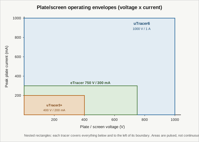
The rectangles nest: the uTracer6 contains the eTracer’s operating area, which contains the uTracer3+‘s. Anything the smaller boxes can do, the 6 can do; the reverse is not true. The practical reading:
- The uTracer3+ stops at 400 V and 200 mA. That covers most small-signal and receiving tubes and plenty of preamp triodes, but it cannot reach the plate voltage or the peak current of a beam-power output tube driven hard.
- The eTracer reaches 750 V and 300 mA — more headroom, enough for many output tubes, but still short of the plate voltages transmitter and TV horizontal-sweep tubes want.
- The uTracer6 goes to 1000 V and 1 A, about 1 kW of pulsed output. That is what puts sweep tubes and beam-power tubes — the 6L6 / KT88 / KT120 family — and transmitter tubes fully inside the measurable area. A KT88 or KT120 in class-AB push-pull swings peak plate currents well above 200 mA, and transmitter and sweep tubes routinely need more than 400 V; the 6 is the box that has both axes at once.
That envelope is the entire reason to own the model, and it is the frame for both comparisons below.
6.4 Comparison: uTracer6 vs the eTracer
The eTracer is the commercial rival that shares the tube-characterisation half of the bench (its own dive covers it in full; cross-link it there). It is an Essues / Chris Chang product from Taiwan, 2017 — an independent design that arrived at the same charge-a-cap-and-pulse idea as Dekker’s uTracer, not a variant of it. Both plot the same kind of curves and both export data a host can turn into SPICE models. The differences are about headroom, form factor, and who does the building.
- Envelope. eTracer 750 V / 300 mA on plate and screen; uTracer6 1000 V / 1 A, approx. 1 kW pulsed. The 6 has the clear headroom advantage — it is the box that reaches transmitter and sweep tubes the eTracer’s 750 V / 300 mA cannot fully exercise.
- Build model. The eTracer is a commercial, largely turnkey instrument; the uTracer6 is a DIY through-hole kit you solder, calibrate, and case yourself (Vol 4). If you want to plug in and measure, that weighs for the eTracer. If you want to understand and own the HV stage down to the SiC switch, the kit is the point.
- Cost. The uTracer6 kit is EUR 329 (plus EUR 80 for the positive-grid extension) and does not include sockets, switches, or a cord — you supply the chassis and the labour. A commercial instrument prices in the assembly and support instead.
- Positive grid. With the extension board the uTracer6 drives the grid to +100 V and measures 0-100 mA of grid current — useful for tubes run into positive-grid territory. Weigh that as a uTracer6 capability; do not assume the eTracer’s positive-grid behaviour here (see the eTracer dive for its actual spec).
- Temperament. The uTracer6’s higher-voltage, higher-current stage is more oscillation-prone, which is why Dekker markets it to experienced builders. A turnkey commercial box aims to hide that from the user.
Net: reach for the uTracer6 when you need the kilovolt envelope or the positive-grid extension, or when building and owning the instrument is part of the goal. Reach for the eTracer when you want a turnkey box and your tubes live inside 750 V / 300 mA.
6.5 Comparison: uTracer6 vs the uTracer3+/NXT lineage
Inside Dekker’s own line, three models matter for this decision. The lineage runs uTracer(v1) 2010 idea -> uTracer3 2012 (300 V) -> uTracer3+ 2015 (400 V) -> [uTracer4/5 failed prototypes] -> uTracer6 approx. 2019-2020 (1000 V / 1 A) -> uTracer7 (development) -> uTracer NXT (current mainstream). Vol 2 tells that story in full; here it is only the decision.
- uTracer3+ — the predecessor the 6 out-ranges. 400 V / 200 mA, approx. 80 W pulsed. Smaller 4 x 6.4 in board, PIC 16F874A, PWM grid supply. It is the baseline the uTracer6 was built to exceed; the NXT has since replaced the 3+ as the model you would actually buy new for audio-tube work.
- uTracer NXT — the current mainstream audio-tube model, a ground-up new design that replaced the uTracer3+, at approx. 450-500 V. Its kit is EUR 239 (EUR 255 PayPal). Dekker’s NXT explicitly incorporated learnings from the uTracer6 and the uTracer7. It is the default for ordinary receiving and audio tubes; its dive is a separate subproject (note it, don’t duplicate it).
- uTracer6 — the parallel high-voltage specialist. 1000 V / 1 A, approx. 1 kW, grid to -100 V (and +100 V with the extension). It is not newer-and-better than the NXT and not the flagship; it is the box you add when the NXT’s approx. 450-500 V is not enough plate voltage or its current ceiling is not enough peak current.
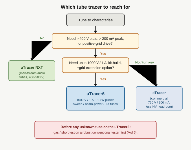
The rule of thumb: default to the NXT for audio and receiving tubes; step up to the uTracer6 only when you actually need more than approx. 400-500 V of plate voltage, more than a couple hundred milliamps of peak current, positive-grid drive, or the transmitter/sweep-tube reach that only the kilovolt envelope gives. The uTracer6 costs more than the NXT (EUR 329 vs EUR 239) and is more oscillation-prone; you take those on in exchange for the envelope, not for a general upgrade.
6.6 Side-by-side comparison table
Table 4 — Side-by-side comparison table
| Attribute | uTracer3+ | uTracer NXT | uTracer6 | eTracer |
|---|---|---|---|---|
| Role in the workflow | superseded audio-tube tracer | current mainstream audio-tube tracer | HV / high-current specialist | commercial audio-tube tracer |
| Plate / screen voltage | 2 to 400 V | approx. 450-500 V (per the NXT dive) | 0 to 1000 V | 0 to 750 V |
| Peak plate / screen current | 0 to 200 mA | not asserted here | up to 1000 mA (approx. 1 A) | 0 to 300 mA |
| Peak pulsed power | approx. 80 W | not asserted here | up to approx. 1 kW | not asserted here |
| Negative grid bias | -50 V to 0 V | not asserted here | 0 to -100 V | see eTracer dive |
| Positive grid | not available | not asserted here | 0 to +100 V (extension board) | see eTracer dive |
| Measurement principle | pulsed cap-discharge | pulsed cap-discharge | pulsed cap-discharge (approx. 1 ms) | pulsed cap-discharge |
| Build model | DIY through-hole kit | DIY kit | DIY through-hole kit | commercial / turnkey |
| Kit / unit price | — | EUR 239 (EUR 255 PayPal) | EUR 329 (EUR 350 PayPal) + EUR 80 ext. | commercial pricing |
| PCB size | 4 x 6.4 in | not asserted here | 6 x 6 in | not asserted here |
| Reach for it when | (legacy) | ordinary audio / receiving tubes | need > approx. 400-500 V, > 200 mA, +grid, TX/sweep tubes | turnkey box within 750 V / 300 mA |
“Not asserted here” marks a cell whose authoritative figure lives in the uTracer NXT or eTracer dive rather than here: the uTracer NXT dive is the authority for the NXT’s voltage, current, power, grid, and board figures, and the eTracer dive for the eTracer’s grid behaviour.
6.7 Bottom line
The uTracer6 earns its place on the bench for exactly one reason, and the whole of this volume points at it: the kilovolt envelope. It is a distinct Dekker model, not a uTracer3 revision and not the current-generation flagship — the NXT holds that role for ordinary tubes. You keep the NXT (or reach for the eTracer) for audio and receiving work inside a few hundred volts, and you power up the uTracer6 when the tube on the socket — a beam-power output tube, a TV sweep tube, a transmitter tube — needs the 1000 V / 1 A, approx. 1 kW pulsed reach that nothing else here can give it. That capability comes with a DIY build, a higher price than the NXT, an oscillation-prone temperament, and a genuine kilovolt shock hazard — roughly 11-12 J stored in EACH 500 V reservoir capacitor, about 25 J across the anode pair at ~1000 V, with the screen rail carrying its own identical reservoir. Respect the discharge discipline (Vol 5), test unknown tubes elsewhere first, and the model does what no smaller tracer on this bench can.